Using the Arduino UNO R4 WiFi LED Matrix
Get off the ground with the Arduino UNO R4 WiFi built-in LED matrix. Learn the different techniques for controlling it, create animations, graphics or even games.
The Arduino UNO R4 WiFi comes with a built in 12x8 LED Matrix, that is available to be programmed to display graphics, animations, act as an interface, or even play games on.
Goals
The matrix and its API are developed to be programmed in a few different ways, each suited for different applications. This guide will walk you through the basic concepts for programming the LED matrix, and get you started with creating your own animations, while highlighting two different ways of handling the LEDs to create animations and images. This makes it easier for you to decide what method fits your needs best!

Hardware & Software Needed
- Arduino UNO R4 WiFi
- UNO R4 Board Package (latest version)
- Arduino IDE
Initializing Matrix
To use the LED Matrix library, there are a few things that need to be added to your sketch to get off the ground.
First, include the library at the top of your sketch, like this:
1#include "Arduino_LED_Matrix.h"Then, you'll need to create a LED Matrix object in your sketch, by adding the following line directly underneath the first one:
1ArduinoLEDMatrix matrix;And then lastly, start the LED Matrix by adding this line in
void setup()1matrix.begin();The entire thing should look like this;
1#include "Arduino_LED_Matrix.h"2
3ArduinoLEDMatrix matrix;4
5void setup() {6 Serial.begin(115200);7 matrix.begin();8}How to Write a Frame
The LED Matrix library for the UNO R4 WiFi works on the principle of creating a frame, and then loading it into a buffer which displays the frame.
A frame is what we call the "image" that is displayed at any given moment on the matrix. If an animation is a series of images, a frame is one of those images in the series.
In order to control the 12x8 LED matrix on the UNO R4 WiFi, you need a space in memory that's at least 96 bits in size. The library provides two ways to do this.
The first is simply to make a two-dimensional array of bytes like so:
1byte frame[8][12] = {2 { 0, 0, 1, 1, 0, 0, 0, 1, 1, 0, 0, 0 },3 { 0, 1, 0, 0, 1, 0, 1, 0, 0, 1, 0, 0 },4 { 0, 1, 0, 0, 0, 1, 0, 0, 0, 1, 0, 0 },5 { 0, 0, 1, 0, 0, 0, 0, 0, 1, 0, 0, 0 },6 { 0, 0, 0, 1, 0, 0, 0, 1, 0, 0, 0, 0 },7 { 0, 0, 0, 0, 1, 0, 1, 0, 0, 0, 0, 0 },8 { 0, 0, 0, 0, 0, 1, 0, 0, 0, 0, 0, 0 },9 { 0, 0, 0, 0, 0, 0, 0, 0, 0, 0, 0, 0 }10};This option is simple to understand, because you can see the image in the pattern of the array, and it is easy to edit in runtime. The ones in the array above form a heart, and that's the image you'd see on the screen.
To target an individual pixel you select its address and change the value, remember that you'll need to start counting at 0. So, the following line will target the third pixel from the left and the second from the top, then turn it on:
1frame[2][1] = 1;2
3matrix.renderBitmap(frame, 8, 12);This method takes more memory than is needed, however. Even though each LED needs only a single bit to store its state, you're using eight bits (a byte). The more memory-efficient method to store a frame is to use an array of 32-bit integers.
In this section we'll walk through the process and the concept of how you may create one of these frames yourself. Though we have developed a tool that can do this for you, so you can click here if you want to skip this exercise.
Here's the same heart in that form:
1unsigned long frame[] = {2 0x3184a444,3 0x42081100,4 0xa00400005};An unsigned long variable holds 32 bits, and 96/32 is 3, so an unsigned long array is an efficient way to hold all the bits you need for the LED matrix.
But how do those hexadecimal values relate to the positions of the pixels? To find out, convert the hexadecimal values to binary values. Here's a code snippet that will do this:
1for (int b = 0; b < 3; b++) {2 Serial.println(frame[b], BIN);3 }This will print out all the bit values of the array. The output will look like this:
111000110000100101001000100010021000010000010000001000100000000310100000000001000000000000000000This method doesn't show you all the bits, though. Each array element should have 32 bits. If you add zeros to show all 32 bits of each element, you get:
100110001100001001010010001000100201000010000010000001000100000000310100000000001000000000000000000Now divide it into groups of 12 bits and you've got the heart back:
10011000110002010010100100301000100010040010000010005000100010000600001010000070000010000008000000000000Hint: You can see the heart easier if you highlight all "1"s on the page by pressing CTRL/command + F and search for "1".
If you've got several different frames, you can load and display them like this:
1const uint32_t happy[] = {2 0x19819,3 0x80000001,4 0x81f80005};6
7const uint32_t heart[] = {8 0x3184a444,9 0x44042081,10 0x100a004011};12
13 matrix.loadFrame(happy);14 delay(500);15
16 matrix.loadFrame(heart);17 delay(500);Testing It Out
Let's apply these concepts, with two basic sketches that display different frames on your board. First, let's create 3x32-bit integer frames and load them one by one.
Here's a sketch that will first load a smiley face on your matrix, and then change it to a heart.
1#include "Arduino_LED_Matrix.h"2
3ArduinoLEDMatrix matrix;4
5void setup() {6 Serial.begin(115200);7 matrix.begin();8}9
10const uint32_t happy[] = {11 0x19819,12 0x80000001,13 0x81f800014};15const uint32_t heart[] = {16 0x3184a444,17 0x44042081,18 0x100a004019};20 21void loop(){22 matrix.loadFrame(happy);23 delay(500);24
25 matrix.loadFrame(heart);26 delay(500);27}The sketch is pretty simple, and yet the outcome is very expressive and can help you easily indicate states of your projects.
Now let's change approach and create a bitmap that we change in runtime. This sketch includes several functions that each draw part of a face, and then winks the left eye by turning off certain pixels.
1#include "Arduino_LED_Matrix.h"2
3ArduinoLEDMatrix matrix;4
5void setup() {6 Serial.begin(115200);7 matrix.begin();8}9
10uint8_t frame[8][12] = {11 { 0, 0, 0, 0, 0, 0, 0, 0, 0, 0, 0, 0 },12 { 0, 0, 0, 0, 0, 0, 0, 0, 0, 0, 0, 0 },13 { 0, 0, 0, 0, 0, 0, 0, 0, 0, 0, 0, 0 },14 { 0, 0, 0, 0, 0, 0, 0, 0, 0, 0, 0, 0 },15 { 0, 0, 0, 0, 0, 0, 0, 0, 0, 0, 0, 0 },16 { 0, 0, 0, 0, 0, 0, 0, 0, 0, 0, 0, 0 },17 { 0, 0, 0, 0, 0, 0, 0, 0, 0, 0, 0, 0 },18 { 0, 0, 0, 0, 0, 0, 0, 0, 0, 0, 0, 0 }19};20
21void leftEye(){22 //Left eye23 frame[1][3] = 1;24 frame[1][4] = 1;25 frame[2][3] = 1;26 frame[2][4] = 1;27}28
29void wink(){30 //Wink with the left eye31 frame[1][3] = 0;32 frame[1][4] = 0;33 frame[2][3] = 1;34 frame[2][4] = 1;35}36
37void rightEye(){38 //Right eye39 frame[1][8] = 1;40 frame[1][9] = 1;41 frame[2][8] = 1;42 frame[2][9] = 1;43}44
45void mouth(){46 //Mouth47 frame[5][3] = 1;48 frame[5][9] = 1;49 frame[6][3] = 1;50 frame[6][4] = 1;51 frame[6][5] = 1;52 frame[6][6] = 1;53 frame[6][7] = 1;54 frame[6][8] = 1;55 frame[6][9] = 1;56}57
58void loop(){59leftEye();60rightEye();61mouth();62
63matrix.renderBitmap(frame, 8, 12);64
65delay(1000);66wink();67
68matrix.renderBitmap(frame, 8, 12);69delay(1000);70}Scrolling Text Example
The LED Matrix now supports printing characters via the ArduinoGraphics library. With it, you are able to:
- Set a start location for the text via
. The "0xFFFFFF" represents the default color (red). As the ArduinoGraphics library supports other hardware with multiple colors, we need to specify it.matrix.beginText(x,y, 0xFFFFFF) - Print the text via
matrix.printText("This message is printed") - End the print and (optionally) specify scroll direction with
matrix.endText(direction)
,SCROLL_LEFT
are supported. Leave blank if no scroll is desired.SCROLL_RIGHT
The example below simply prints out "Hello World!" on the matrix.
1// To use ArduinoGraphics APIs, please include BEFORE Arduino_LED_Matrix2#include "ArduinoGraphics.h"3#include "Arduino_LED_Matrix.h"4
5ArduinoLEDMatrix matrix;6
7void setup() {8 Serial.begin(115200);9 matrix.begin();10
11 matrix.beginDraw();12 matrix.stroke(0xFFFFFFFF);13 // add some static text14 // will only show "UNO" (not enough space on the display)15 const char text[] = "UNO r4";16 matrix.textFont(Font_4x6);17 matrix.beginText(0, 1, 0xFFFFFF);18 matrix.println(text);19 matrix.endText();20
21 matrix.endDraw();22
23 delay(2000);24}25
26void loop() {27
28 // Make it scroll!29 matrix.beginDraw();30
31 matrix.stroke(0xFFFFFFFF);32 matrix.textScrollSpeed(50);33
34 // add the text35 const char text[] = " Hello World! ";36 matrix.textFont(Font_5x7);37 matrix.beginText(0, 1, 0xFFFFFF);38 matrix.println(text);39 matrix.endText(SCROLL_LEFT);40
41 matrix.endDraw();42}Animation Generation
We have developed a tool that is used to generate frames and animations to be rendered on the LED Matrix in your browser. This tool is part of Arduino labs, and is therefore considered experimental software.
To use the tool you need to upload the following sketch, allowing the board to read serial inputs send by the browser.
You can also find the sketch in File > Examples > LED_Matrix > LivePreview
1#include "Arduino_LED_Matrix.h"2
3ArduinoLEDMatrix matrix;4
5void setup() {6 Serial.begin(115200);7 matrix.begin();8}9
10uint32_t frame[] = {11 0, 0, 0, 0xFFFF12};13
14void loop() {15 if(Serial.available() >= 12){16 frame[0] = Serial.read() | Serial.read() << 8 | Serial.read() << 16 | Serial.read() << 24;17 frame[1] = Serial.read() | Serial.read() << 8 | Serial.read() << 16 | Serial.read() << 24;18 frame[2] = Serial.read() | Serial.read() << 8 | Serial.read() << 16 | Serial.read() << 24;19 matrix.loadFrame(frame);20 }21}Click here to go to the LED Matrix tool.
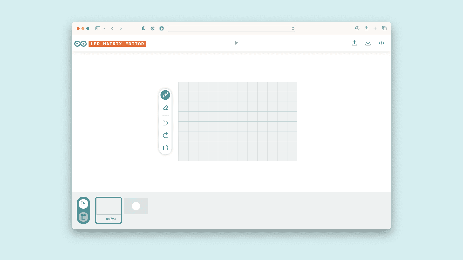
Once you've made your animations, you can export them from the tool in the format that lets you use them like previously discussed.
You can find more tips on how to use this tool on its site.
Conclusion
In this article we've gone over the basics of using the LED Matrix built in on the Arduino UNO R4 WiFi, we've gone over the different practices for building frames and animations, as well as how to load them onto your board.
Have fun creating interactive interfaces or animation on your UNO R4 WiFi!
API
To write more advanced sketches on your own, you may use the full API of the library as found below.
| Members | Descriptions |
|---|---|
| The main class for controlling the LED matrix. |
| Sets the time in ms for each frame to be displayed. |
| Start the LED matrix. |
| Manually move to the next frame in the sequence. |
| Load a new single frame that is not in any sequence. |
| Render the loaded frame. |
| Loads an animation sequence into the buffer but does not display it. |
| Start playing the sequence of frames, with the option to loop indefinitely or play once. |
| checks if the sequence has finished playing. |
Members
ArduinoLEDMatrix()
ArduinoLEDMatrix()Construct a new LED matrix object. This will be used to access the methods in the library.
1ArduinoLEDMatrix LEDMatrix;autoscroll()
autoscroll()Enable autoscrolling through the frames in a sequence.
Parameters
Sets the time in milliseconds that should be spent on a frame before switching to the next frame in the sequence.interval_ms
begin()
begin()Starts the LED matrix.
1LEDMatrix.begin()next()
next()Manually moves to the next frame in the sequence.
1LEDMatrix.next()loadFrame()
loadFrame()Loads a single frame that is not part of a sequence.
1LEDMatrix.loadFrame(buffer[i])Parameters
an array of three 32bit integers, where each bit represents an LED.buffer[3]
renderFrame()
renderFrame()Render a specific frame from a sequence.
1LEDMatrix.renderFrame(frameNumber)Parameters
- frame to load.int
loadSequence()
loadSequence()Loads an animation sequence into the buffer but does not display it.
1LEDMatrix.frames[][4]Parameters
Specifies which frame of the sequence should be rendered.frameNumber
play()
play()Starts playing the loaded sequence.
1LEDMatrix.play(state) //true or falseParameters
true to enable looping the sequence, false to play once.loop
sequenceDone()
sequenceDone()Check for if the sequence is finished playing or if the frame should be advanced another step.
Returns
if the sequence is not finished,false
if it is.true
Suggest changes
The content on docs.arduino.cc is facilitated through a public GitHub repository. If you see anything wrong, you can edit this page here.
License
The Arduino documentation is licensed under the Creative Commons Attribution-Share Alike 4.0 license.