Examples by Board
Find examples that work only with specific boards, such as reading built-in sensors.
In this article, you will find examples that works only with specific boards. Each board also has a GPIO map that explains how each pin can be addressed.
Nano RP2040 Connect
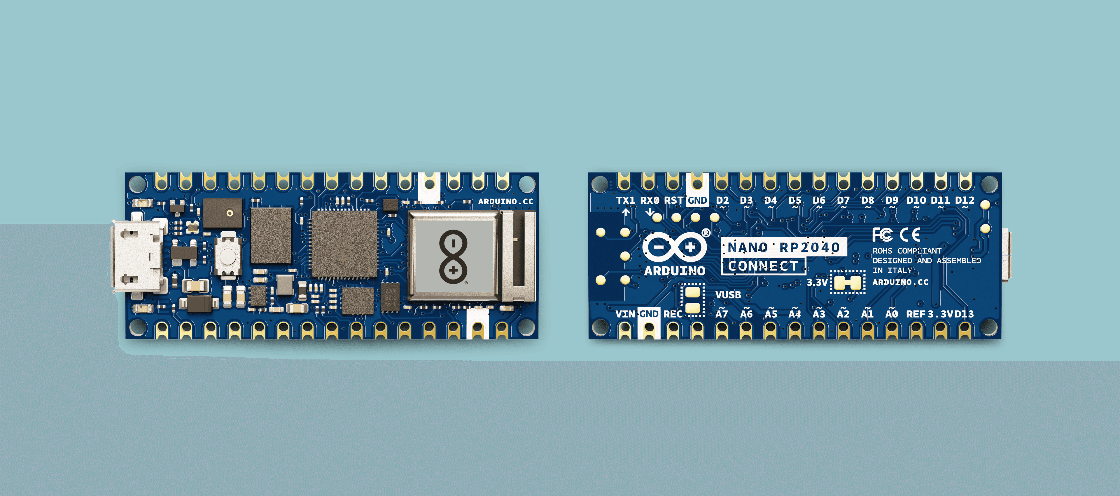
GPIO Map
The pinout for the Nano RP2040 Connect and the RP2040 microcontroller varies greatly. For example, if we are to use
D21# Defining "D2" on the Arduino Nano RP2040 Connect2p0 = Pin(25, Pin.OUT)Before you start using the board's pins, it might be a good idea to check out the table below to understand the relationship between Arduino's pinout and the RP2040's pinout.
| Arduino | RP2040 | Usage |
|---|---|---|
| TX | GPIO0 | UART/TX |
| RX | GPIO1 | UART/RX |
| D2 | GPIO25 | GPIO |
| D3 | GPIO15 | GPIO |
| D4 | GPIO16 | GPIO |
| D5 | GPIO17 | GPIO |
| D6 | GPIO18 | GPIO |
| D7 | GPIO19 | GPIO |
| D8 | GPIO20 | GPIO |
| D9 | GPIO21 | GPIO |
| D10 | GPIO5 | GPIO |
| D11 | GPIO7 | SPI/COPI |
| D12 | GPIO4 | SPI/CIPO |
| D13 | GPIO6 | SPI/SCK |
| D14/A0 | GPIO26 | ADC/RP2040 |
| D15/A1 | GPIO27 | ADC/RP2040 |
| D16/A2 | GPIO28 | ADC/RP2040 |
| D17/A3 | GPIO29 | ADC/RP2040 |
| D18/A4 | GPIO12 | I2C |
| D19/A5 | GPIO13 | I2C |
| D20/A6 | GPIO36 | ADC/NINA-W102 |
| D21/A7 | GPIO35 | ADC/NINA-W102 |
Analog Read
Note: This is currently only available on the nightly build. Follow this link to download it.
To read an analog pin, we can use the
ADC.read_u16ADCmachine1from machine import ADC2
3while True:4 adc = ADC("A4")5 adc.read_u16()Sensors
IMU (LSM6DSOX)
Prints the accelerometer and gyroscope values in the Serial Monitor.
1import time2from lsm6dsox import LSM6DSOX3
4from machine import Pin, I2C5lsm = LSM6DSOX(I2C(0, scl=Pin(13), sda=Pin(12)))6
7while (True):8 print('Accelerometer: x:{:>8.3f} y:{:>8.3f} z:{:>8.3f}'.format(*lsm.read_accel()))9 print('Gyroscope: x:{:>8.3f} y:{:>8.3f} z:{:>8.3f}'.format(*lsm.read_gyro()))10 print("")11 time.sleep_ms(100)Microphone (MP34DT05)
Below example can be used with OpenMV's frame buffer window (top right corner).
1import image, audio, time2from ulab import numpy as np3from ulab import scipy as sp4
5CHANNELS = 16FREQUENCY = 320007N_SAMPLES = 32 if FREQUENCY == 16000 else 648SCALE = 29SIZE = (N_SAMPLES * SCALE) // CHANNELS10
11raw_buf = None12fb = image.Image(SIZE+(50*SCALE), SIZE, image.RGB565, copy_to_fb=True)13audio.init(channels=CHANNELS, frequency=FREQUENCY, gain_db=16)14
15def audio_callback(buf):16 # NOTE: do Not call any function that allocates memory.17 global raw_buf18 if (raw_buf == None):19 raw_buf = buf20
21# Start audio streaming22audio.start_streaming(audio_callback)23
24def draw_fft(img, fft_buf):25 fft_buf = (fft_buf / max(fft_buf)) * SIZE26 fft_buf = np.log10(fft_buf + 1) * 2027 color = (0xFF, 0x0F, 0x00)28 for i in range(0, len(fft_buf)):29 img.draw_line(i*SCALE, SIZE, i*SCALE, SIZE-int(fft_buf[i]) * SCALE, color, SCALE)30
31def draw_audio_bar(img, level, offset):32 blk_size = (SIZE//10)33 color = (0xFF, 0x00, 0xF0)34 blk_space = (blk_size//4)35 for i in range(0, int(round(level/10))):36 fb.draw_rectangle(SIZE+offset, SIZE - ((i+1)*blk_size) + blk_space, 20 * SCALE, blk_size - blk_space, color, 1, True)37
38while (True):39 if (raw_buf != None):40 pcm_buf = np.frombuffer(raw_buf, dtype=np.int16)41 raw_buf = None42
43 if CHANNELS == 1:44 fft_buf = sp.signal.spectrogram(pcm_buf)45 l_lvl = int((np.mean(abs(pcm_buf[1::2])) / 32768)*100)46 else:47 fft_buf = sp.signal.spectrogram(pcm_buf[0::2])48 l_lvl = int((np.mean(abs(pcm_buf[1::2])) / 32768)*100)49 r_lvl = int((np.mean(abs(pcm_buf[0::2])) / 32768)*100)50
51 fb.clear()52 draw_fft(fb, fft_buf)53 draw_audio_bar(fb, l_lvl, 0)54 draw_audio_bar(fb, l_lvl, 25*SCALE)55 if CHANNELS == 2:56 draw_audio_bar(fb, r_lvl, 25 * SCALE)57 fb.flush()58
59# Stop streaming60audio.stop_streaming()Communication
I2C
Scans for devices connected to the I2C buses:
1import time2from machine import Pin, I2C3
4i2c_list = [None, None]5i2c_list[0] = I2C(0, scl=Pin(13), sda=Pin(12), freq=100_000)6i2c_list[1] = I2C(1, scl=Pin(7), sda=Pin(6), freq=100_000)7
8for bus in range(0, 2):9 print("\nScanning bus %d..."%(bus))10 for addr in i2c_list[bus].scan():11 print("Found device at address %d:0x%x" %(bus, addr))UART
To read data and write data through TX and RX pins, you can use
uart.write()uart.read()1from machine import UART, Pin2import time3
4uart = UART(0, baudrate=9600, tx=Pin(0), rx=Pin(1))5
6while True:7 uart.write('hello') # writes 5 bytes8 val = uart.read(5) # reads up to 5 bytes9 print(val) # prints data10 time.sleep(1)Wireless
Below are examples on wireless connectivity, using the NINA-W102 module onboard the Nano RP2040 Connect.
In order to use these examples, you may have to upgrade your firmware. You can find instructions on how to in Upgrading Nano RP2040 Connect NINA firmware.
Wi-Fi AP Mode
Turn your board into an access point:
1# Wi-Fi AP Mode Example2#3# This example shows how to use Wi-Fi in Access Point mode.4import network, socket, sys, time, gc5
6SSID ='My_Nano_RP2040_Connect' # Network SSID7KEY ='1234567890' # Network key (must be 10 chars)8HOST = '' # Use first available interface9PORT = 8080 # Arbitrary non-privileged port10
11# Init wlan module and connect to network12wlan = network.WLAN(network.AP_IF)13wlan.active(True)14wlan.config(essid=SSID, key=KEY, security=wlan.WEP, channel=2)15print("AP mode started. SSID: {} IP: {}".format(SSID, wlan.ifconfig()[0]))16
17def recvall(sock, n):18 # Helper function to recv n bytes or return None if EOF is hit19 data = bytearray()20 while len(data) < n:21 packet = sock.recv(n - len(data))22 if not packet:23 raise OSError("Timeout")24 data.extend(packet)25 return data26
27def start_streaming(server):28 print ('Waiting for connections..')29 client, addr = server.accept()30
31 # set client socket timeout to 5s32 client.settimeout(5.0)33 print ('Connected to ' + addr[0] + ':' + str(addr[1]))34
35 # FPS clock36 clock = time.clock()37 while (True):38 try:39 # Read data from client40 data = recvall(client, 1024)41 # Send it back42 client.send(data)43 except OSError as e:44 print("start_streaming(): socket error: ", e)45 client.close()46 break47
48while (True):49 try:50 server = socket.socket(socket.AF_INET, socket.SOCK_STREAM)51 # Bind and listen52 server.bind([HOST, PORT])53 server.listen(1)54
55 # Set server socket to blocking56 server.setblocking(True)57 while (True):58 start_streaming(server)59 except OSError as e:60 server.close()61 print("Server socket error: ", e)Wi-Fi® Scan
To scan available networks:
1# Scan Example2
3# This example shows how to scan for Wi-Fi networks.4
5import time, network6
7wlan = network.WLAN(network.STA_IF)8wlan.active(True)9
10print("Scanning...")11while (True):12 scan_result = wlan.scan()13 for ap in scan_result:14 print("Channel:%d RSSI:%d Auth:%d BSSID:%s SSID:%s"%(ap))15 print()16 time.sleep_ms(1000)HTTP Request
Making an HTTP request (in this case to google):
Remember to enter your network name and password inside the SSID and KEY variables.
1import network, socket2
3# AP info4SSID='' # Network SSID5KEY='' # Network key6
7PORT = 808HOST = "www.google.com"9
10# Init wlan module and connect to network11print("Trying to connect. Note this may take a while...")12
13wlan = network.WLAN(network.STA_IF)14wlan.active(True)15wlan.connect(SSID, KEY)16
17# We should have a valid IP now via DHCP18print("Wi-Fi Connected ", wlan.ifconfig())19
20# Get addr info via DNS21addr = socket.getaddrinfo(HOST, PORT)[0][4]22print(addr)23
24# Create a new socket and connect to addr25client = socket.socket(socket.AF_INET, socket.SOCK_STREAM)26client.connect(addr)27
28# Set timeout29client.settimeout(3.0)30
31# Send HTTP request and recv response32client.send("GET / HTTP/1.1\r\nHost: %s\r\n\r\n"%(HOST))33print(client.recv(1024))34
35# Close socket36client.close()NTP (Network Time Protocol)
Remember to enter your network name and password inside the SSID and KEY variables.
Obtain accurate time and date from the Internet:
1# NTP Example2#3# This example shows how to get the current time using NTP4
5import network, usocket, ustruct, utime6
7# AP info8SSID='' # Network SSID9KEY='' # Network key10
11TIMESTAMP = 220898880012
13# Init wlan module and connect to network14print("Trying to connect... (may take a while)...")15
16wlan = network.WLAN()17wlan.active(True)18wlan.connect(SSID, key=KEY, security=wlan.WPA_PSK)19
20# We should have a valid IP now via DHCP21print(wlan.ifconfig())22
23# Create new socket24client = usocket.socket(usocket.AF_INET, usocket.SOCK_DGRAM)25client.bind(("", 8080))26#client.settimeout(3.0)27
28# Get addr info via DNS29addr = usocket.getaddrinfo("pool.ntp.org", 123)[0][4]30
31# Send query32client.sendto('\x1b' + 47 * '\0', addr)33data, address = client.recvfrom(1024)34
35# Print time36t = ustruct.unpack(">IIIIIIIIIIII", data)[10] - TIMESTAMP37print ("Year:%d Month:%d Day:%d Time: %d:%d:%d" % (utime.localtime(t)[0:6]))In the terminal, we should see it in this format:
1Year:2021 Month:8 Day:10 Time: 7:56:30Bluetooth® Low Energy
This example allows us to connect to our board via our phone, and control the built-in LED. We recommend using the nRF Connect applications.
After loading the script below, your board should be listed as "Nano RP2040 Connect" in the list of available devices. You need to pair in order to control the built-in LED.
1import bluetooth2import random3import struct4import time5from ble_advertising import advertising_payload6from machine import Pin7from micropython import const8
9LED_PIN = 610
11_IRQ_CENTRAL_CONNECT = const(1)12_IRQ_CENTRAL_DISCONNECT = const(2)13_IRQ_GATTS_WRITE = const(3)14
15_FLAG_READ = const(0x0002)16_FLAG_WRITE = const(0x0008)17_FLAG_NOTIFY = const(0x0010)18_FLAG_INDICATE = const(0x0020)19
20_SERVICE_UUID = bluetooth.UUID(0x1523)21_LED_CHAR_UUID = (bluetooth.UUID(0x1525), _FLAG_WRITE)22_LED_SERVICE = (_SERVICE_UUID, (_LED_CHAR_UUID,),)23
24class BLETemperature:25 def __init__(self, ble, name="NANO RP2040"):26 self._ble = ble27 self._ble.active(True)28 self._ble.irq(self._irq)29 ((self._handle,),) = self._ble.gatts_register_services((_LED_SERVICE,))30 self._connections = set()31 self._payload = advertising_payload(name=name, services=[_SERVICE_UUID])32 self._advertise()33
34 def _irq(self, event, data):35 # Track connections so we can send notifications.36 if event == _IRQ_CENTRAL_CONNECT:37 conn_handle, _, _ = data38 self._connections.add(conn_handle)39 elif event == _IRQ_CENTRAL_DISCONNECT:40 conn_handle, _, _ = data41 self._connections.remove(conn_handle)42 # Start advertising again to allow a new connection.43 self._advertise()44 elif event == _IRQ_GATTS_WRITE:45 Pin(LED_PIN, Pin.OUT).value(int(self._ble.gatts_read(data[-1])[0]))46 47 def _advertise(self, interval_us=500000):48 self._ble.gap_advertise(interval_us, adv_data=self._payload)49
50if __name__ == "__main__":51 ble = bluetooth.BLE()52 temp = BLETemperature(ble)53 54 while True:55 time.sleep_ms(1000)Nano 33 BLE
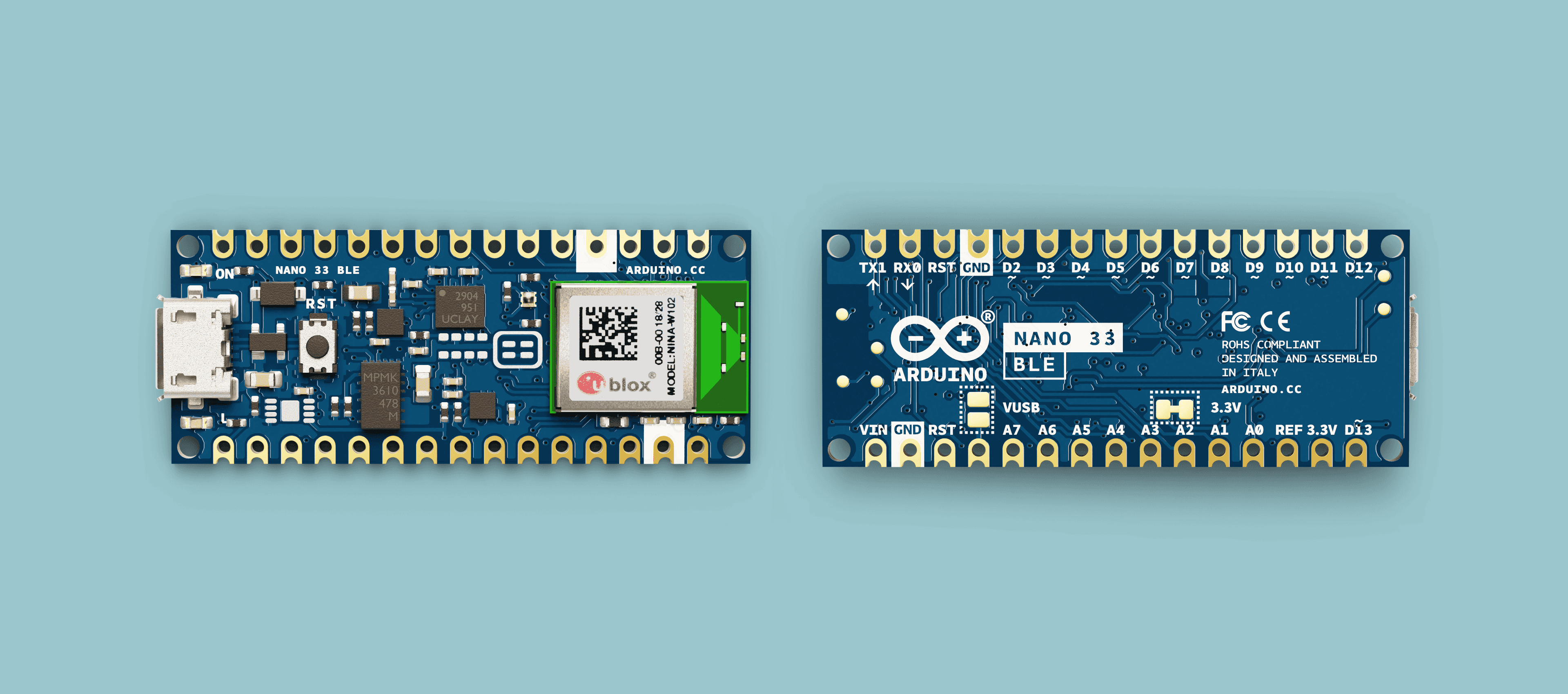
GPIO Map
The pinout for the Nano 33 BLE and the NRF52840 microcontroller varies greatly. For example, if we are to use
D21# Defining "D2" on the Nano 33 BLE2p0 = Pin(43, Pin.OUT)In the MicroPython port of the Nano 33 BLE board, the pinout is the same as the Nordic NRF52840 (the microcontroller). You will find a GPIO Map below that explains how to address the different pins.
| Arduino | nRF52840 |
|---|---|
| TX | 35 |
| RX | 42 |
| D2 | 43 |
| D3 | 44 |
| D4 | 47 |
| D5 | 45 |
| D6 | 46 |
| D7 | 23 |
| D8 | 21 |
| D9 | 27 |
| D10 | 34 |
| D11 | 33 |
| D12 | 40 |
| D13 | 13 |
| D14/A0 | 4 |
| D15/A1 | 5 |
| D16/A2 | 30 |
| D17/A3 | 29 |
| D18/A4 | 31 |
| D19/A5 | 2 |
| D20/A6 | 28 |
| D21/A7 | 3 |
Analog Read
The following example is currently only possible with the nightly build
LED Control
There are 3 different LEDs that can be accessed on the Nano 33 BLE: RGB, the built-in LED and the power LED.
They can be accessed by importing the
LED1from board import LED2
3led_red = LED(1) # red LED4led_green = LED(2) # green LED5led_blue = LED(3) # blue LED6led_builtin = LED(4) # classic built-in LED (also accessible through pin 13)To access the power LED we need to import the
Pin1from machine import Pin2
3led_pwr = Pin(41, Pin.OUT)RGB
Blink all RGB lights every 0.25 seconds.
1from board import LED2import time 3
4led_red = LED(1)5led_green = LED(2)6led_blue = LED(3)7
8while (True):9 10 # Turn on LEDs11 led_red.on()12 led_green.on()13 led_blue.on()14
15 # Wait 0.25 seconds16 time.sleep_ms(250)17 18 # Turn off LEDs19 led_red.off()20 led_green.off()21 led_blue.off()22
23 # Wait 0.25 seconds24 time.sleep_ms(250)Built-in LED
The classic blink example! Blink the built-in LED every 0.25 seconds.
1from board import LED2import time 3
4led_builtin = LED(4)5
6while (True):7 8 # Turn on LED9 led_builtin.on()10
11 # Wait 0.25 seconds12 time.sleep_ms(250)13 14 # Turn off LED15 led_builtin.off()16
17 # Wait 0.25 seconds18 time.sleep_ms(250)Sensors
IMU (LSM9DS1, BMI270 + BMM150)
Access the
accelerometermagnetometergyroscope1import time2import imu3from machine import Pin, I2C4
5bus = I2C(1, scl=Pin(15), sda=Pin(14))6imu = imu.IMU(bus)7
8while (True):9 print('Accelerometer: x:{:>8.3f} y:{:>8.3f} z:{:>8.3f}'.format(*imu.accel()))10 print('Gyroscope: x:{:>8.3f} y:{:>8.3f} z:{:>8.3f}'.format(*imu.gyro()))11 print('Magnetometer: x:{:>8.3f} y:{:>8.3f} z:{:>8.3f}'.format(*imu.magnet()))12 print("")13 time.sleep_ms(100)Wireless
Bluetooth® Low Energy
This example allows us to connect to our board via our phone, and control the built-in LED. We recommend using the nRF Connect applications.
After loading the script below, your board should be listed as "Nano 33 BLE" in the list of available devices. You need to pair in order to control the built-in LED.
1# Use nRF Connect from App store, connect to the Nano and write 1/0 to control the LED.2
3import time4from board import LED5from ubluepy import Service, Characteristic, UUID, Peripheral, constants6
7def event_handler(id, handle, data):8 global periph9 global service10 if id == constants.EVT_GAP_CONNECTED:11 pass12 elif id == constants.EVT_GAP_DISCONNECTED:13 # restart advertisement14 periph.advertise(device_name="Nano 33 BLE", services=[service])15 elif id == constants.EVT_GATTS_WRITE:16 LED(1).on() if int(data[0]) else LED(1).off()17
18# start off with LED(1) off19LED(1).off()20
21notif_enabled = False22uuid_service = UUID("0x1523")23uuid_led = UUID("0x1525")24
25service = Service(uuid_service)26char_led = Characteristic(uuid_led, props=Characteristic.PROP_WRITE)27service.addCharacteristic(char_led)28
29periph = Peripheral()30periph.addService(service)31periph.setConnectionHandler(event_handler)32periph.advertise(device_name="Nano 33 BLE", services=[service])33
34while (True):35 time.sleep_ms(500)Nano 33 BLE Sense
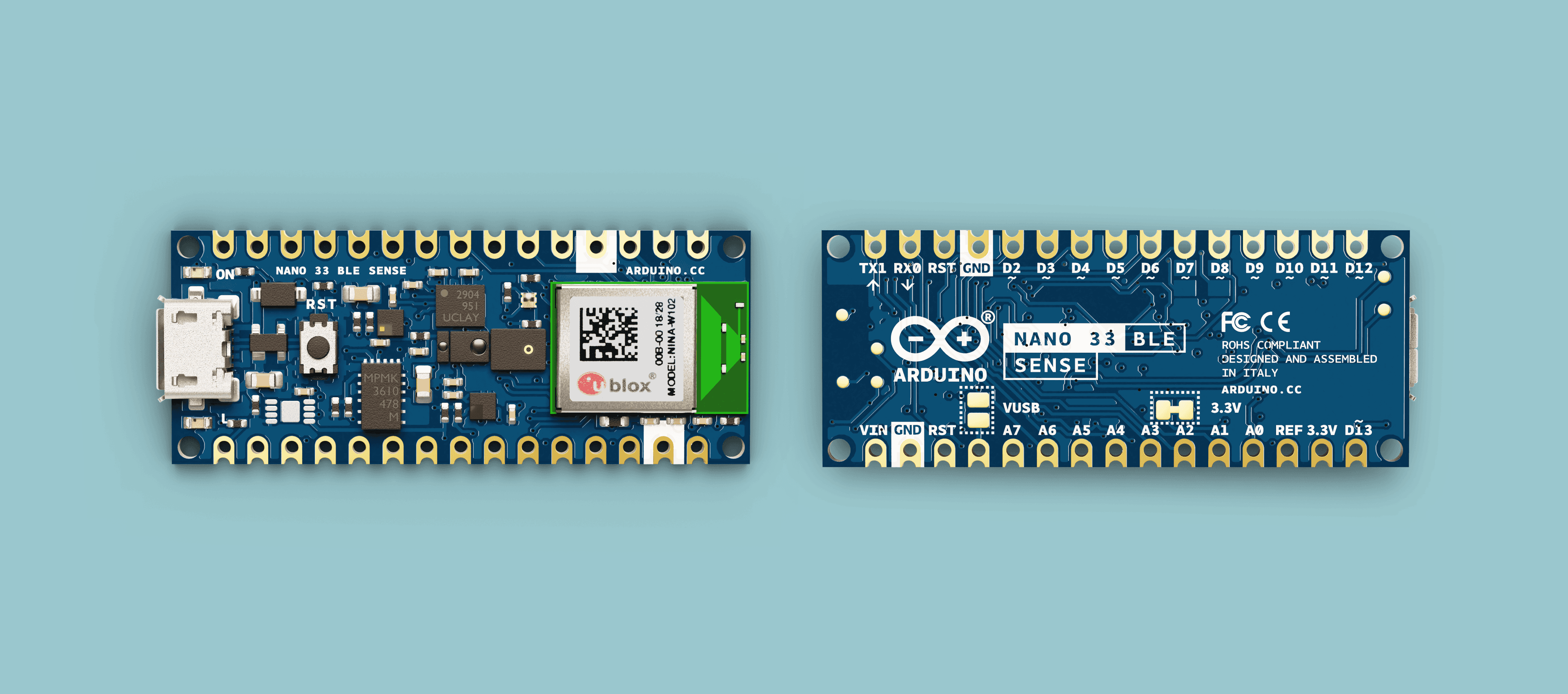
Pin Map
The pinout for the Nano 33 BLE Sense and the NRF52840 microcontroller varies greatly. For example, if we are to use
D21# Defining "D2" on the Nano 33 BLE Sense2p0 = Pin(43, Pin.OUT)In the MicroPython port of the Nano 33 BLE Sense board, the pinout is the same as the Nordic NRF52840 (the microcontroller). You will find a pin map below this section that explains how to address the different pins.
| Arduino | nRF52840 |
|---|---|
| TX | 35 |
| RX | 42 |
| D2 | 43 |
| D3 | 44 |
| D4 | 47 |
| D5 | 45 |
| D6 | 46 |
| D7 | 23 |
| D8 | 21 |
| D9 | 27 |
| D10 | 34 |
| D11 | 33 |
| D12 | 40 |
| D13 | 13 |
| D14/A0 | 4 |
| D15/A1 | 5 |
| D16/A2 | 30 |
| D17/A3 | 29 |
| D18/A4 | 31 |
| D19/A5 | 2 |
| D20/A6 | 28 |
| D21/A7 | 3 |
LED Control
There are 3 different LEDs that can be accessed on the Nano 33 BLE Sense: RGB, the built-in LED and the power LED.
They can be accessed by importing the
LED1from board import LED2
3led_red = LED(1) # red LED4led_green = LED(2) # green LED5led_blue = LED(3) # blue LED6led_builtin = LED(4) # classic built-in LED (also accessible through pin 13)To access the power LED we need to import the
Pin1from machine import Pin2
3led_pwr = Pin(41, Pin.OUT)RGB
Blink all RGB lights every 0.25 seconds.
1from board import LED2import time 3
4led_red = LED(1)5led_green = LED(2)6led_blue = LED(3)7
8while (True):9 10 # Turn on LEDs11 led_red.on()12 led_green.on()13 led_blue.on()14
15 # Wait 0.25 seconds16 time.sleep_ms(250)17 18 # Turn off LEDs19 led_red.off()20 led_green.off()21 led_blue.off()22
23 # Wait 0.25 seconds24 time.sleep_ms(250)Built-in LED
The classic blink example! Blink the built-in LED every 0.25 seconds.
1from board import LED2import time 3
4led_builtin = LED(4)5
6while (True):7 8 # Turn on LED9 led_builtin.on()10
11 # Wait 0.25 seconds12 time.sleep_ms(250)13 14 # Turn off LED15 led_builtin.off()16
17 # Wait 0.25 seconds18 time.sleep_ms(250)Sensors
There are several sensors onboard the Nano 33 BLE Sense. The scripts below can be used to access the data from each of them.
IMU (LSM9DS1, BMI270 + BMM150)
Access the
accelerometermagnetometergyroscope1import time2import imu3from machine import Pin, I2C4
5bus = I2C(1, scl=Pin(15), sda=Pin(14))6imu = imu.IMU(bus)7
8while (True):9 print('Accelerometer: x:{:>8.3f} y:{:>8.3f} z:{:>8.3f}'.format(*imu.accel()))10 print('Gyroscope: x:{:>8.3f} y:{:>8.3f} z:{:>8.3f}'.format(*imu.gyro()))11 print('Magnetometer: x:{:>8.3f} y:{:>8.3f} z:{:>8.3f}'.format(*imu.magnet()))12 print("")13 time.sleep_ms(100)Temperature & Humidity (HTS221)
Access the
temperaturehumidity1import time2import hts2213from machine import Pin, I2C4
5bus = I2C(1, scl=Pin(15), sda=Pin(14))6hts = hts221.HTS221(bus)7
8while (True):9 rH = hts.humidity()10 temp = hts.temperature()11 print ("rH: %.2f%% T: %.2fC" %(rH, temp))12 time.sleep_ms(100)Pressure (LPS22)
Access the
pressure1import time2import lps22h3from machine import Pin, I2C4
5bus = I2C(1, scl=Pin(15), sda=Pin(14))6lps = lps22h.LPS22H(bus)7
8while (True):9 pressure = lps.pressure()10 temperature = lps.temperature()11 print("Pressure: %.2f hPa Temperature: %.2f C"%(pressure, temperature))12 time.sleep_ms(100)Ambient Light (APDS9960)
Access the
Ambient Light1from time import sleep_ms2from machine import Pin, I2C3from apds9960.const import *4from apds9960 import uAPDS9960 as APDS99605
6bus = I2C(1, sda=Pin(13), scl=Pin(14))7apds = APDS9960(bus)8
9print("Light Sensor Test")10print("=================")11apds.enableLightSensor()12
13while True:14 sleep_ms(250)15 val = apds.readAmbientLight()16 print("AmbientLight={}".format(val))Proximity (APDS9960)
Access the
Proximity values1from time import sleep_ms2from machine import Pin, I2C3
4from apds9960.const import *5from apds9960 import uAPDS9960 as APDS99606
7bus = I2C(1, sda=Pin(13), scl=Pin(14))8apds = APDS9960(bus)9
10apds.setProximityIntLowThreshold(50)11
12print("Proximity Sensor Test")13print("=====================")14apds.enableProximitySensor()15
16while True:17 sleep_ms(250)18 val = apds.readProximity()19 print("proximity={}".format(val))Microphone (MP34DT05)
Below example can be used with OpenMV's frame buffer window (top right corner).
1import image, audio, time2from ulab import numpy as np3from ulab import scipy as sp4
5CHANNELS = 16SIZE = 256//(2*CHANNELS)7
8raw_buf = None9fb = image.Image(SIZE+50, SIZE, image.RGB565, copy_to_fb=True)10audio.init(channels=CHANNELS, frequency=16000, gain_db=80, highpass=0.9883)11
12def audio_callback(buf):13 # NOTE: do Not call any function that allocates memory.14 global raw_buf15 if (raw_buf == None):16 raw_buf = buf17
18# Start audio streaming19audio.start_streaming(audio_callback)20
21def draw_fft(img, fft_buf):22 fft_buf = (fft_buf / max(fft_buf)) * SIZE23 fft_buf = np.log10(fft_buf + 1) * 2024 color = (0xFF, 0x0F, 0x00)25 for i in range(0, SIZE):26 img.draw_line(i, SIZE, i, SIZE-int(fft_buf[i]), color, 1)27
28def draw_audio_bar(img, level, offset):29 blk_size = SIZE//1030 color = (0xFF, 0x00, 0xF0)31 blk_space = (blk_size//4)32 for i in range(0, int(round(level/10))):33 fb.draw_rectangle(SIZE+offset, SIZE - ((i+1)*blk_size) + blk_space, 20, blk_size - blk_space, color, 1, True)34
35while (True):36 if (raw_buf != None):37 pcm_buf = np.frombuffer(raw_buf, dtype=np.int16)38 raw_buf = None39
40 if CHANNELS == 1:41 fft_buf = sp.signal.spectrogram(pcm_buf)42 l_lvl = int((np.mean(abs(pcm_buf[1::2])) / 32768)*100)43 else:44 fft_buf = sp.signal.spectrogram(pcm_buf[0::2])45 l_lvl = int((np.mean(abs(pcm_buf[1::2])) / 32768)*100)46 r_lvl = int((np.mean(abs(pcm_buf[0::2])) / 32768)*100)47
48 fb.clear()49 draw_fft(fb, fft_buf)50 draw_audio_bar(fb, l_lvl, 0)51 if CHANNELS == 2:52 draw_audio_bar(fb, r_lvl, 25)53 fb.flush()54
55# Stop streaming56audio.stop_streaming()Wireless
Bluetooth® Low Energy
This example allows us to connect to our board via our phone, and control the built-in LED. We recommend using the nRF Connect applications.
After loading the script below, your board should be listed as "Nano 33 BLE Sense" in the list of available devices. You need to pair in order to control the built-in LED.
1# Use nRF Connect from App store, connect to the Nano and write 1/0 to control the LED.2
3import time4from board import LED5from ubluepy import Service, Characteristic, UUID, Peripheral, constants6
7def event_handler(id, handle, data):8 global periph9 global service10 if id == constants.EVT_GAP_CONNECTED:11 pass12 elif id == constants.EVT_GAP_DISCONNECTED:13 # restart advertisement14 periph.advertise(device_name="Nano 33 BLE Sense", services=[service])15 elif id == constants.EVT_GATTS_WRITE:16 LED(1).on() if int(data[0]) else LED(1).off()17
18# start off with LED(1) off19LED(1).off()20
21notif_enabled = False22uuid_service = UUID("0x1523")23uuid_led = UUID("0x1525")24
25service = Service(uuid_service)26char_led = Characteristic(uuid_led, props=Characteristic.PROP_WRITE)27service.addCharacteristic(char_led)28
29periph = Peripheral()30periph.addService(service)31periph.setConnectionHandler(event_handler)32periph.advertise(device_name="Nano 33 BLE Sense", services=[service])33
34while (True):35 time.sleep_ms(500)Portenta H7
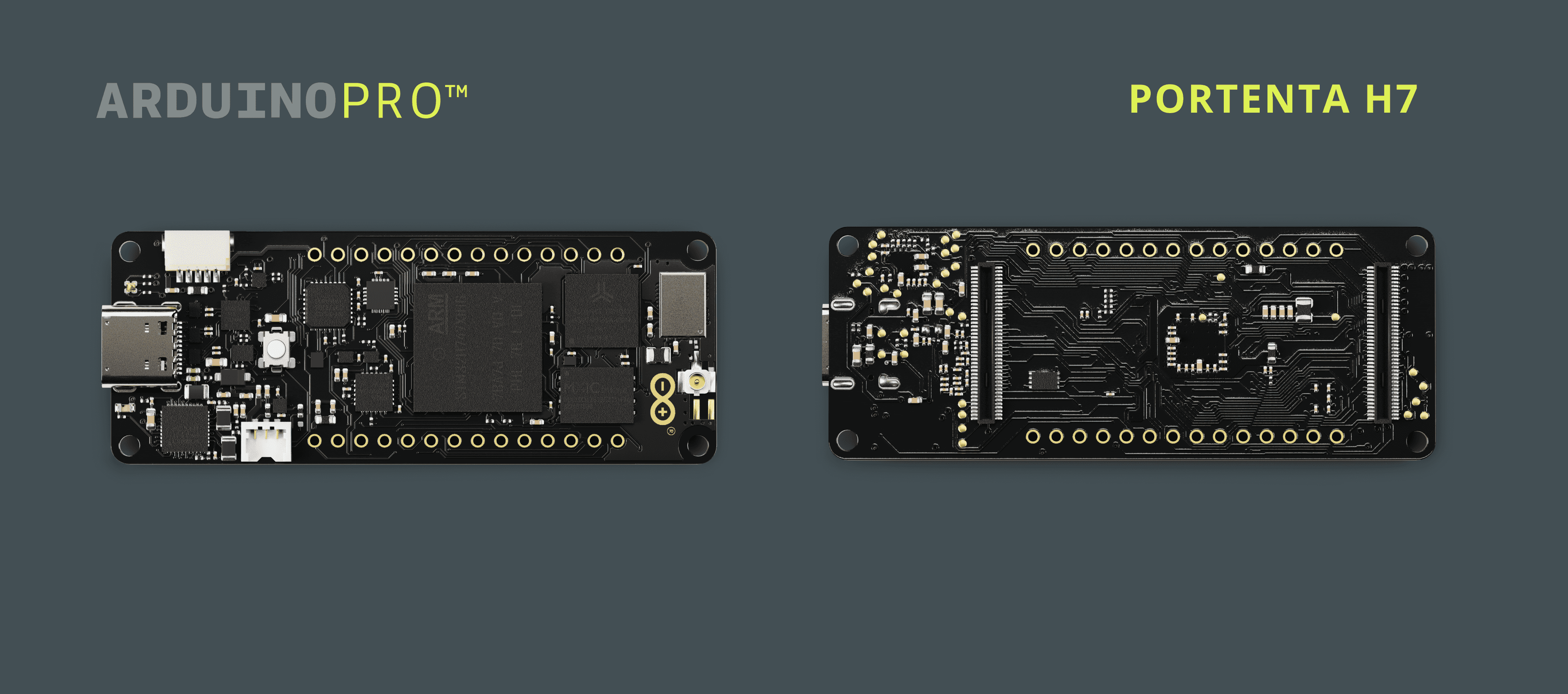
Note that the Portenta H7 Lite and Portenta H7 Lite Connected boards are compatible with most examples listed here, as they are variations of the Portenta H7.
GPIO Map
Most of the pins are referred to via their port name or their function. Please refer to the list below to see which function corresponds to which port on the Portenta H7.
| Arduino | STM32H747 |
|---|---|
| PA0 | PA0 |
| PA1 | PA1 |
| PA2 | PA2 |
| PA3 | PA3 |
| PA4 | PA4 |
| PA5 | PA5 |
| PA6 | PA6 |
| PA7 | PA7 |
| PA8 | PA8 |
| PA9 | PA9 |
| PA10 | PA10 |
| PA11 | PA11 |
| PA12 | PA12 |
| PA13 | PA13 |
| PA14 | PA14 |
| PA15 | PA15 |
| PB0 | PB0 |
| PB1 | PB1 |
| PB2 | PB2 |
| PB3 | PB3 |
| PB4 | PB4 |
| PB5 | PB5 |
| PB6 | PB6 |
| PB7 | PB7 |
| PB8 | PB8 |
| PB9 | PB9 |
| PB10 | PB10 |
| PB11 | PB11 |
| PB12 | PB12 |
| PB13 | PB13 |
| PB14 | PB14 |
| PB15 | PB15 |
| PC0 | PC0 |
| PC1 | PC1 |
| PC2 | PC2 |
| PC3 | PC3 |
| PC4 | PC4 |
| PC5 | PC5 |
| PC6 | PC6 |
| PC7 | PC7 |
| PC8 | PC8 |
| PC9 | PC9 |
| PC10 | PC10 |
| PC11 | PC11 |
| PC12 | PC12 |
| PC13 | PC13 |
| PC14 | PC14 |
| PC15 | PC15 |
| PD0 | PD0 |
| PD1 | PD1 |
| PD2 | PD2 |
| PD3 | PD3 |
| PD4 | PD4 |
| PD5 | PD5 |
| PD6 | PD6 |
| PD7 | PD7 |
| PD8 | PD8 |
| PD9 | PD9 |
| PD10 | PD10 |
| PD11 | PD11 |
| PD12 | PD12 |
| PD13 | PD13 |
| PD14 | PD14 |
| PD15 | PD15 |
| PE0 | PE0 |
| PE1 | PE1 |
| PE2 | PE2 |
| PE3 | PE3 |
| PE4 | PE4 |
| PE5 | PE5 |
| PE6 | PE6 |
| PE7 | PE7 |
| PE8 | PE8 |
| PE9 | PE9 |
| PE10 | PE10 |
| PE11 | PE11 |
| PE12 | PE12 |
| PE13 | PE13 |
| PE14 | PE14 |
| PE15 | PE15 |
| PF0 | PF0 |
| PF1 | PF1 |
| PF2 | PF2 |
| PF3 | PF3 |
| PF4 | PF4 |
| PF5 | PF5 |
| PF6 | PF6 |
| PF7 | PF7 |
| PF8 | PF8 |
| PF9 | PF9 |
| PF10 | PF10 |
| PF11 | PF11 |
| PF12 | PF12 |
| PF13 | PF13 |
| PF14 | PF14 |
| PF15 | PF15 |
| PG0 | PG0 |
| PG1 | PG1 |
| PG2 | PG2 |
| PG3 | PG3 |
| PG4 | PG4 |
| PG5 | PG5 |
| PG6 | PG6 |
| PG7 | PG7 |
| PG8 | PG8 |
| PG9 | PG9 |
| PG10 | PG10 |
| PG11 | PG11 |
| PG12 | PG12 |
| PG13 | PG13 |
| PG14 | PG14 |
| PG15 | PG15 |
| PH0 | PH0 |
| PH1 | PH1 |
| PH2 | PH2 |
| PH3 | PH3 |
| PH4 | PH4 |
| PH5 | PH5 |
| PH6 | PH6 |
| PH7 | PH7 |
| PH8 | PH8 |
| PH9 | PH9 |
| PH10 | PH10 |
| PH11 | PH11 |
| PH12 | PH12 |
| PH13 | PH13 |
| PH14 | PH14 |
| PH15 | PH15 |
| PI0 | PI0 |
| PI1 | PI1 |
| PI2 | PI2 |
| PI3 | PI3 |
| PI4 | PI4 |
| PI5 | PI5 |
| PI6 | PI6 |
| PI7 | PI7 |
| PI8 | PI8 |
| PI9 | PI9 |
| PI10 | PI10 |
| PI11 | PI11 |
| PI12 | PI12 |
| PI13 | PI13 |
| PI14 | PI14 |
| PI15 | PI15 |
| PJ0 | PJ0 |
| PJ1 | PJ1 |
| PJ2 | PJ2 |
| PJ3 | PJ3 |
| PJ4 | PJ4 |
| PJ5 | PJ5 |
| PJ6 | PJ6 |
| PJ7 | PJ7 |
| PJ8 | PJ8 |
| PJ9 | PJ9 |
| PJ10 | PJ10 |
| PJ11 | PJ11 |
| PJ12 | PJ12 |
| PJ13 | PJ13 |
| PJ14 | PJ14 |
| PJ15 | PJ15 |
| PK0 | PK0 |
| PK1 | PK1 |
| PK2 | PK2 |
| PK3 | PK3 |
| PK4 | PK4 |
| PK5 | PK5 |
| PK6 | PK6 |
| PK7 | PK7 |
| UART1_TX | PA9 |
| UART1_RX | PA10 |
| UART4_TX | PA0 |
| UART4_RX | PI9 |
| UART6_TX | PG14 |
| UART6_RX | PG9 |
| UART8_TX | PJ8 |
| UART8_RX | PJ9 |
| ETH_RMII_REF_CLK | PA1 |
| ETH_MDIO | PA2 |
| ETH_RMII_CRS_DV | PA7 |
| ETH_MDC | PC1 |
| ETH_RMII_RXD0 | PC4 |
| ETH_RMII_RXD1 | PC5 |
| ETH_RMII_TX_EN | PG11 |
| ETH_RMII_TXD0 | PG13 |
| ETH_RMII_TXD1 | PG12 |
| USB_HS_CLK | PA5 |
| USB_HS_STP | PC0 |
| USB_HS_NXT | PH4 |
| USB_HS_DIR | PI11 |
| USB_HS_D0 | PA3 |
| USB_HS_D1 | PB0 |
| USB_HS_D2 | PB1 |
| USB_HS_D3 | PB10 |
| USB_HS_D4 | PB11 |
| USB_HS_D5 | PB12 |
| USB_HS_D6 | PB13 |
| USB_HS_D7 | PB5 |
| USB_HS_RST | PJ4 |
| USB_DM | PA11 |
| USB_DP | PA12 |
| BOOT0 | BOOT0 |
| DAC1 | PA4 |
| DAC2 | PA5 |
| LEDR | PK5 |
| LEDG | PK6 |
| LEDB | PK7 |
| I2C1_SDA | PB7 |
| I2C1_SCL | PB6 |
| I2C3_SDA | PH8 |
| I2C3_SCL | PH7 |
| -WL_REG_ON | PJ1 |
| -WL_HOST_WAKE | PJ5 |
| -WL_SDIO_0 | PC8 |
| -WL_SDIO_1 | PC9 |
| -WL_SDIO_2 | PC10 |
| -WL_SDIO_3 | PC11 |
| -WL_SDIO_CMD | PD2 |
| -WL_SDIO_CLK | PC12 |
| -BT_RXD | PF6 |
| -BT_TXD | PA15 |
| -BT_CTS | PF9 |
| -BT_RTS | PF8 |
| -BT_REG_ON | PJ12 |
| -BT_HOST_WAKE | PJ13 |
| -BT_DEV_WAKE | PJ14 |
| -QSPI2_CS | PG6 |
| -QSPI2_CLK | PF10 |
| -QSPI2_D0 | PD11 |
| -QSPI2_D1 | PD12 |
| -QSPI2_D2 | PF7 |
| -QSPI2_D3 | PD13 |
I/O Pins
To access the I/O pins, you can use the
Pinpyb1from pyb import PinTo reference a pin on the Portenta, you can use the
Pin()modePin.INPin.OUT_PPPin.OUT_ODPin.AF_PPPin.AF_ODPin.ANALOGpullPin.PULL_NONEPin.PULL_UPPin.PULL_DOWN1pin0 = Pin('P0', mode, pull)To get the logic level of a pin, call
.value()LOWHIGH1pin0.value()PWM
To use PWM, you import the
pybtimePinTimer1import pyb2import time3from pyb import Pin, TimerFirst you need to choose the pin you want to use PWM with.
1pin1 = Pin("PC6", Pin.OUT_PP, Pin.PULL_NONE)Create a timer for the PWM, where you set the ID and the frequency.
1timer1 = Timer(3, freq=1000)Then you need to start a PWM channel with the timer object.
1channel1 = timer1.channel(1, Timer.PWM, pin=pin1, pulse_width=0)Get or set the pulse width value on a channel. To get, pass no arguments. To set, give a value as an argument.
1channel1.pulse_width(Width)RGB LED
The Portenta H7 has built-in RGB that can be used as feedback for applications. Using the
pybFor this you will use the
pyb1import pybNow you can easily define the different colors of the built in LED.
1redLED = pyb.LED(1)2greenLED = pyb.LED(2)3blueLED = pyb.LED(3)And then control them in our script.
1redLED.on()2redLED.off()3
4greenLED.on()5greenLED.off()6
7blueLED.on()8blueLED.off()You could also set a custom intensity for our LED lights. This ranges between the values 0 (off) and 255 (full on). Below you can see an example of how to set the intensity on our different LED lights.
1redLED.intensity(128)2greenLED.intensity(64)3blueLED.intensity(50)If no argument is given in the
.intensity()Communication
Like other Arduino® products, the Portenta H7 features dedicated pins for different protocols.
SPI
The pins used for SPI on the Portenta H7 are the following:
| Pin | Function |
|---|---|
| PI0 | CS |
| PC3 | COPI |
| PI1 | CK |
| PC2 | CIPO |
You can refer to the pinout above to find them on the board.
First, you have to import the relevant module from
pyb1from pyb import SPIWhen you initialize SPI, the only thing you need to state is the bus, which will always be
2SPI.MASTERSPI.SLAVEbaudratePolarityPhase1spi = SPI(2, SPI.MASTER, baudrate=100000, polarity=0, phase=0)Now, if you want to send data over SPI, you simply call
.send()datatimeout1dataInt = 212dataBuffer = bytearray(4)3spi.send(data, timeout=5000)Similarly, if you want to receive data over SPI, you call
.recv()datatimeout1dataInt = 02dataBuffer = bytearray(4)3SPI.recv(data, timeout=5000)I2C
The pins used for I2C (Inter-Integrated Circuit) on the Portenta H7 are the following:
| Pin | Function |
|---|---|
| PH8 | SDA |
| PH7 | SCL |
You can refer to the pinout above to find them on the board.
To use the I2C, you import the relevant module.
1from pyb import I2CYou can now create the I2C object. To create an I2C object you need to state the bus, this indicates what pins you will use for I2C. Giving bus a value of
31i2c = I2C(3)Now that the object is created, you can initialize it. You need to decide if your device is going to be a controller (I2C.MASTER) or a reader (I2C.SLAVE). If it is a reader device, you also need to set the
address1i2c.init(I2C.MASTER, addr=address, baudrate=100000)To receive data on the bus, you call the
.recv()dataaddrtimeout1dataInt = 02dataBuffer = bytearray(4)3receivedData = i2c.recv(data, addr=0, timeout=5000)4Print(receivedData)To send data on the bus, you can call the
.send()dataaddrtimeout1dataInt = 4122dataBuffer = bytearray(4)3i2c.send(data, addr=0, timeout=5000)If you need to make sure that devices are connected to the I2C bus, you can use the
.scan()1i2c.scan()UART
The pins used for UART on the Portenta H7 are the following:
| Pin | Function |
|---|---|
| PA10 | RX |
| PA9 | TX |
You can refer to the pinout above to find them on the board.
To use the UART, you need to import the relevant module.
1from pyb import UARTTo create the UART object, you need to indicate the UART bus, the Portenta has 3 UART buses, but there is only on UART bus available to use with OpenMV through the boards pins.
1uart = UART(1)With the object created, you can initialize it with
initbaudratebitsparityNone01stopflowtimeouttimeout_charread_buf_len1uart.init(baudrate, bits=8, parity=None, stop=1, timeout=0, flow=0, timeout_char=0, read_buf_len=64)To read from UART, you can call
.read()bytesbytes1array = bytearray(5)2uart.read(array)3print(array)If you intend to write over UART, you can call
.write()bufferbuffer1uart.write(buffer)Wi-Fi®
To use Wi-Fi® you first need to import the relevant library.
1import networkThen you need to define the Wi-Fi® networks SSID and put that in a variable. You must do the same for the networks password.
1SSID=''2PASSWORD=''Next, you can create a WLAN network interface object. In the argument you can enter
network.STA_IF1wlan = network.WLAN(network.STA_IF)To activate the network interface, you can simply call
.activateTrue1wlan.active(True)Now you can decide which network to connect to. Here it is where the
SSIDPASSWORD1wlan.connect(SSID, PASSWORD, timeout=30000)If you need to troubleshoot, the connection
.status()1wlan.status()Audio
If you want to use audio with the Portenta H7, you first need to include the
audiomicro_speech1import audio, micro_speechNext you need to initialize the audio object. In the initialization you can decide how many
channelsgain_dbhighpass1audio.init(channels=2, frequency=16000, gain_db=24, highpass=0.9883)If you need to deinitialize the audio object, you can simply call
deint()1audio.deint()To use micro_speech, you first need to create a micro_speech object. You can create this object in the variable
speech1speech = micro_speech.MicroSpeech()Next you can start streaming audio into the
micro_speechaudio.start_streaming()micro_speech1audio.start_streaming(speech.audio_callback)If you need to stop the audio streaming, you can call
.stop_streaming()1audio.stop_streaming()Portenta C33
Pinout Mapping
The Portenta C33 has two ways its pins are physically available: through its MKR-styled connectors and its High-Density connectors. Most pins are referred to via their port name or function. In the image below, the Portenta C33 MKR-styled connectors pinout is shown.
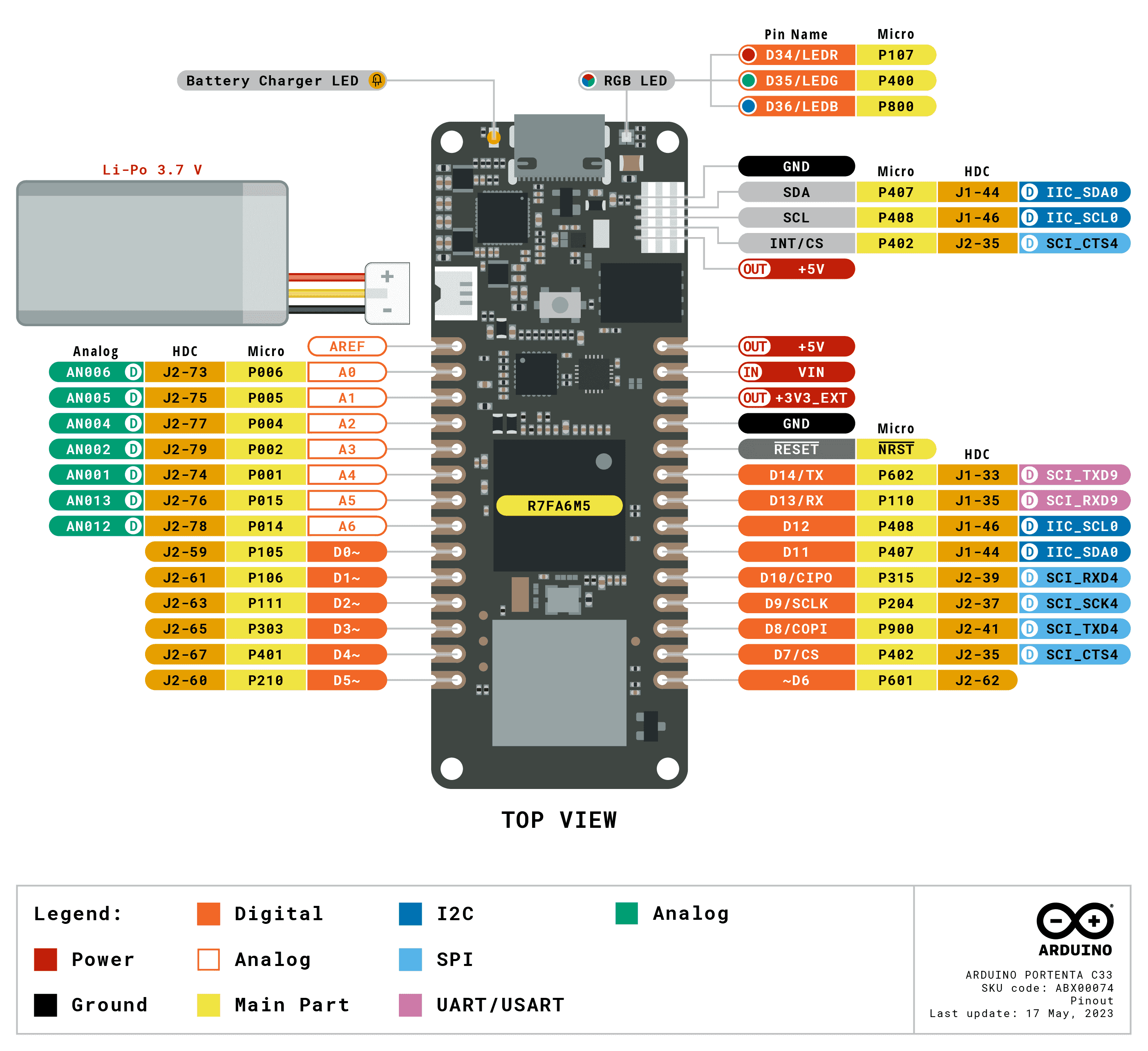
The MKR-styled connectors pinout is mapped in MicroPython as follows:
| Arduino Pin Mapping | MicroPython Pin Mapping |
|---|---|
| |
| |
| |
| |
| |
| |
| |
| |
| |
| |
| |
| |
| |
| |
| |
| |
| |
| |
| |
| |
| |
| |
The complete MicroPython pinout is available here.
Input/Output Pins
The
PinmachinePin Initialization
To begin using an I/O pin of the Portenta C33 board with MicroPython, you need to initialize it using the
Pinmachine1from machine import Pin2
3# Initializing pin P107 as an output4p107 = Pin('P107', Pin.OUT)Configuring Pin Modes
You can configure a pin as an input or output. For input pins, it's often useful to activate an internal pull-up or pull-down resistor. This helps to stabilize the input signal, especially in cases where the pin is reading a mechanical switch or a button.
1# Configuring pin P105 as an input with its pull-up resistor enabled2p105 = Pin('P105', Pin.IN, Pin.PULL_UP)Reading from and Writing to Pins
To read a digital value from a pin, use the
.value().value()1HIGH0LOW1# Reading from P1052pin_value = p105.value()3
4# Writing to P1075p107.value(1) # Set p2 to highAdvanced Pin Configuration
The Pin class allows dynamic reconfiguration of pins and setting up interrupt callbacks. This feature is essential for creating responsive and interactive applications.
1# Reconfiguring P105 as an input with a pull-down resistor2p105.init(Pin.IN, Pin.PULL_DOWN)3
4# Setting up an interrupt on P1055p105.irq(lambda p: print("- IRQ triggered!", p))Practical Example
In this example, we will configure one pin as an input to read the state of a button and another pin as an output to control an LED. The LED will turn on when the button is pressed and off when it's released.
1from machine import Pin2import time3
4# Configure pin P107 as an output (for the LED)5led = Pin('P107', Pin.OUT_PP)6
7# Configure pin P105 as input with pull-up resistor enabled (for the button)8button = Pin('P105', Pin.IN, Pin.PULL_UP)9
10while True:11 # Read the state of the button12 button_state = button.value() 13 if button_state == 0:14 # Turn on LED if button is pressed (button_state is LOW)15 led.value(1) 16 else:17 # Turn off LED if button is not pressed (button_state is HIGH)18 led.value(0) 19
20 # Short delay to debounce the button 21 time.sleep(0.1)This practical example demonstrates controlling an LED based on a button's state. The LED, connected to pin
P107P105Analog to Digital Converter
The
ADCADCThe available ADC pins of the Portenta C33 board in MicroPython are the following:
| Available ADC Pins |
|---|
|
|
|
|
|
|
|
|
Initializing the ADC
First, to use an ADC of the Portenta C33 board, create an ADC object associated with a specific pin. This pin will be used to read analog values.
1from machine import ADC2
3# Create an ADC object on a specific pin4adc = ADC(pin)Reading Analog Values
You can read analog values as raw values using the
read_u16()1# Reading a raw analog value2val = adc.read_u16()Practical Example
This example demonstrates the use of the
ADCGND3V3P0061from machine import ADC, Pin2import time3
4# Initialize the ADC on the potentiometer-connected pin5pot_pin = Pin('P006')6pot_adc = ADC(pot_pin)7
8while True:9 # Read the raw analog value10 raw_value = pot_adc.read_u16()11 print("- Potentiometer raw value:", raw_value)12
13 # Delay for readability14 time.sleep(0.1)The example starts by importing the necessary modules and setting up the ADC on a pin connected to a potentiometer (
P006pot_adcread_u16()065535Pulse Width Modulation
Pulse Width Modulation (PWM) is a method to emulate an analog output using a digital pin. It does this by rapidly toggling the pin between low and high states. Two primary aspects define PWM behavior:
- Frequency: This is the speed at which the pin toggles between low and high states. A higher frequency means the pin toggles faster.
- Duty cycle: This refers to the ratio of the high state duration to the total cycle duration. A 100% duty cycle means the pin remains high all the time, while a 0% duty cycle means it stays low.
The available PWM pins of the Portenta C33 board in MicroPython are the following:
| Available PWM Pins |
|---|
|
|
|
|
|
|
Setting Up PWM
To use PWM, start by initializing a pin and then creating a PWM object associated with that pin.
1import machine2
3# Initialize a pin for PWM (e.g., pin P105)4p105 = machine.Pin('P105')5pwm1 = machine.PWM(p105)Configuring PWM Parameters
The frequency and duty cycle of the PWM signal are set based on the specific needs of your application:
1# Set the frequency to 500 Hz2pwm1.freq(500)3
4# Adjusting the duty cycle to 50 for 50% duty5pwm1.duty(50)Checking PWM Configuration
You can check the current configuration of the PWM object by printing it:
1# Will show the current frequency and duty cycle2print(pwm1)Retrieve the frequency and duty cycle values:
1current_freq = pwm1.freq()2current_duty = pwm1.duty()Deinitializing PWM
When PWM is no longer needed, the pin can be deinitialized:
1pwm1.deinit()Practical Example
In this example, we will use PWM to control the brightness of an LED connected to pin
P1051import machine2import time3
4# Configure the LED pin and PWM5led_pin = machine.Pin('P105')6led_pwm = machine.PWM(led_pin)7led_pwm.freq(500)8
9# Loop to vary brightness10while True:11 # Increase brightness12 for duty in range(100):13 led_pwm.duty(duty)14 time.sleep(0.001)15
16 # Decrease brightness17 for duty in range(100, -1, -1):18 led_pwm.duty(duty)19 time.sleep(0.001)Real-Time Clock
The
RTCInitializing the RTC
To use the RTC, first create an RTC object. This object is then used to set or read the current date and time.
1import machine2
3# Create an RTC object4rtc = machine.RTC()Setting and Getting Date and Time
The RTC allows you to set and retrieve the current date and time. The date and time are represented as an 8-tuple format.
1# Setting the RTC date and time2rtc.datetime((2024, 1, 4, 4, 20, 0, 0, 0))3
4# Getting the current date and time5current_datetime = rtc.datetime()6print("- Current date and time:", current_datetime)The 8-tuple for the date and time follows the format
(year, month, day, weekday, hours, minutes, seconds, subseconds)Practical Example
A practical use case for the RTC is to add timestamps to sensor data readings. By setting the current time on the RTC, you can then append an accurate timestamp each time a sensor value is logged.
1import machine2
3# Initialize the RTC and set the current datetime4rtc.datetime((2024, 1, 4, 4, 20, 0, 0, 0))5
6# Function to read a sensor value (placeholder)7def read_sensor():8 # Replace with actual sensor reading logic9 return 42 10
11# Read sensor value and get the current time12sensor_value = read_sensor()13timestamp = rtc.datetime()14
15# Output the sensor value with its timestamp16print("- Sensor value at ", timestamp, ":", sensor_value)In this example, every sensor reading is accompanied by a timestamp, which can be crucial for data analysis or logging purposes. The RTC's ability to maintain time independently of the main system's power status makes it reliable for time-sensitive applications.
Suggest changes
The content on docs.arduino.cc is facilitated through a public GitHub repository. If you see anything wrong, you can edit this page here.
License
The Arduino documentation is licensed under the Creative Commons Attribution-Share Alike 4.0 license.