Getting Started With the Portenta Vision Shield Camera
This tutorial shows you how to capture frames from the Portenta Vision Shield Camera module and visualize the video output through a Processing sketch.
Overview
This tutorial shows you how to capture frames from the Arduino Portenta Vision Shield Camera module and visualize the video output through a Processing sketch.
Goals
- Capturing the frames from the camera
- Sending the frames as a byte stream through a Serial connection
- Visualising the frames in Processing
Required Hardware and Software
- Portenta H7
- Portenta Vision Shield (LoRa or Ethernet)
- 1x USB-C® cable (either USB-A to USB-C® or USB-C® to USB-C®)
- Arduino IDE 1.8.10+
- Processing 3.5.4+
Instructions
Accessing the Portenta Vision Shield's camera data is done with the help of both Arduino and the Processing IDE. The Arduino sketch handles the capture of image data by the on-board camera, while the java applet created with Processing helps to visualize this data with the help of a serial connection. The following steps will run you through how to capture, package the data through the serial port and visualize the output in Processing.
1. The Basic Setup
Connect the Portenta Vision Shield to your Portenta H7 as shown in the figure. The top and bottom high density connecters are connected to the corresponding ones on the underside of the H7 board. Plug in the H7 to your computer using the USB-C® cable.

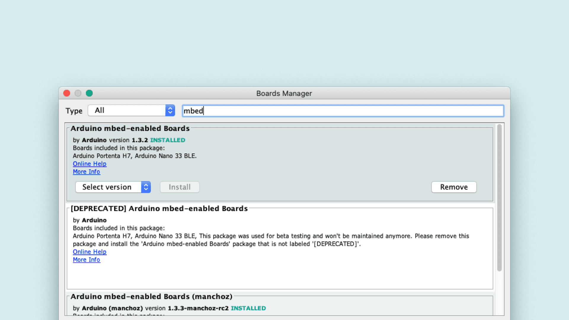
Open the board manager in the Arduino IDE and install the latest version of the Portenta Core which is v1.3.2
2. Capturing the Frames
Create a new Arduino sketch called
CameraCaptureRawBytes.inoTo capture the frames you will need to use the functions contained in
camera.h1#include "camera.h"2#include "himax.h"Next, let's initialize a camera object and a frame buffer of the size 320*240 (76'800 bytes).
1HM01B0 himax;2Camera cam(himax);3#define IMAGE_MODE CAMERA_GRAYSCALE4FrameBuffer fb(320,240,2);5
6unsigned long lastUpdate = 0;In the
setup()921600cam.begin()1void setup() {2 Serial.begin(921600);3 //Init the cam QVGA, 30FPS4 cam.begin(CAMERA_R320x240, IMAGE_MODE, 30);5}In the loop you need to capture each Frame and send it over a serial connection to the Processing sketch that will display the frames. You will use the
grab(uint8_t *buffer, uint32_t timeout=5000);1void loop() {2 // put your main code here, to run repeatedly:3 if(!Serial) { 4 Serial.begin(921600);5 while(!Serial);6 }7 8 // Time out after 2 seconds and send new data9 bool timeoutDetected = millis() - lastUpdate > 2000;10
11 // Wait until the receiver acknowledges12 // that they are ready to receive new data13 if(!timeoutDetected && Serial.read() != 1) return;14
15 lastUpdate = millis();16 17 // Grab frame and write to serial18 if (cam.grabFrame(fb, 3000) == 0) {19 Serial.write(fb.getBuffer(), cam.frameSize());20 }21}3. Create the Processing Sketch
Open a new processing sketch file and name it
CameraCapture.pde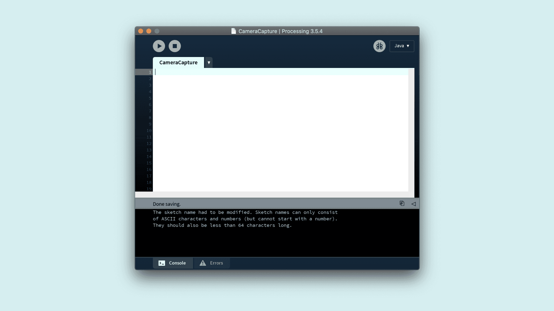
Let's start by importing the libraries and initializing the variables you will need to process. To process the data sent by the Portenta Vision Shield, you will need to import the following libraries:
: a Serial Library that is used to read and write data to external devices over the serial line.processing.serial.*
: a java class that provides access to operations on byte buffersjava.nio.ByteBuffer
1import processing.serial.*;2import java.nio.ByteBuffer;Next, you can initialize the following variables to process the received pixels from the serial port. You can set the dimensions, pixel count and bytes required per frame.
1// must match resolution used in the sketch2final int cameraWidth = 320;3final int cameraHeight = 240;4final int cameraBytesPerPixel = 1;5final int cameraPixelCount = cameraWidth * cameraHeight;6final int bytesPerFrame = cameraWidth * cameraHeight * cameraBytesPerPixel;To receive the frames, you will need a Serial port, a PImage object and an array to store the pixel values of the frame. Add the following variables to the code.
1Serial myPort;2PImage myImage;3byte[] frameBuffer = new byte[bytesPerFrame];4int pixelPosition = 0;5int lastUpdate = 0;6boolean shouldRedraw = false;Here, you will establish a connection to the serial port and prepare the buffer to store the frame pixels. Additionally, you can send a byte to the Arduino sketch from Processing to let it know that it is ready to receive data.
1void setup() {2 size(640, 480);3 4 // if you know the serial port name5 //myPort = new Serial(this, "COM5", 921600); // Windows6 //myPort = new Serial(this, "/dev/ttyACM0", 921600); // Linux7 myPort = new Serial(this, "/dev/cu.usbmodem14101", 921600); // Mac8 9 // Set the number of bytes to buffer 10 myPort.buffer(bytesPerFrame)11 12 // Create an image based on the camera's dimensions and format13 myImage = createImage(cameraWidth, cameraHeight, ALPHA);14
15 // Let the Arduino sketch know we're ready to receive data16 myPort.write(1);17}The draw function checks if the connection is still alive and if there is any new data that can be drawn as an image. In that case, the original image gets copied into a new image object so that it can be scaled up.
1void draw() {2 // Time out after 1.5 seconds and ask for new data3 if(millis() - lastUpdate > 1500) {4 println("Connection timed out.");5 myPort.clear();6 myPort.write(1);7 }8 9 if(shouldRedraw){ 10 PImage img = myImage.copy();11 img.resize(640, 480);12 image(img, 0, 0);13 shouldRedraw = false;14 }15}4. Visualizing the Frames
For this step, you will use the
serialEvent()myImage1void serialEvent(Serial myPort) {2 lastUpdate = millis();3 4 // read the received bytes5 myPort.readBytes(frameBuffer);6
7 // Access raw bytes via byte buffer 8 ByteBuffer bb = ByteBuffer.wrap(frameBuffer);9
10 int i = 0;11
12 while (bb.hasRemaining()) {13 // read 8-bit pixel14 byte pixelValue = bb.get();15
16 // set pixel color17 myImage.pixels[i++] = color(Byte.toUnsignedInt(pixelValue)); 18 }19 20 myImage.updatePixels();21 22 // Ensures that the new image data is drawn in the next draw loop23 shouldRedraw = true;24 25 // Let the Arduino sketch know we received all pixels26 // and are ready for the next frame27 myPort.write(1);28}The first thing you can do inside this method is to update the timestamp when the last data was read. This is to detect and recover from a connection timeout. Then read the bytes from the
frameBufferreadBytes()1lastUpdate = millis();2 3// read the received bytes4myPort.readBytes(frameBuffer);Then the frame buffer is translated into a ByteBuffer that allows for easy and safe access to the underlying bytes without having to worry about the array indices.
1// Access raw bytes via byte buffer 2ByteBuffer bb = ByteBuffer.wrap(frameBuffer);Next we read the frame buffer and convert the bytes into pixel color values. The image gets constructed by sequentially filling the pixels array of the image. The conversion of the raw data is done with
and color()
.Byte.toUnsignedInt()
1int i = 0;2
3while (bb.hasRemaining()) {4 // read 8-bit pixel5 byte pixelValue = bb.get();6
7 // set pixel color8 myImage.pixels[i++] = color(Byte.toUnsignedInt(pixelValue)); 9}Once all the pixels have been updated, you need to tell the sketch to redraw the image. Additionally, you can send an acknowledgement back to the arduino sketch to ask it to send the pixels for the next frame. You can update the image with
updatePixels()11myImage.updatePixels();2
3// Ensures that the new image data is drawn in the next draw loop4shouldRedraw = true;5
6// Let the Arduino sketch know we received all pixels7// and are ready for the next frame8myPort.write(1);5. Upload the Sketch
Select the right serial port on your IDE and upload the Arduino sketch to your Portenta H7. After a successful upload, run the
CameraViewer.pde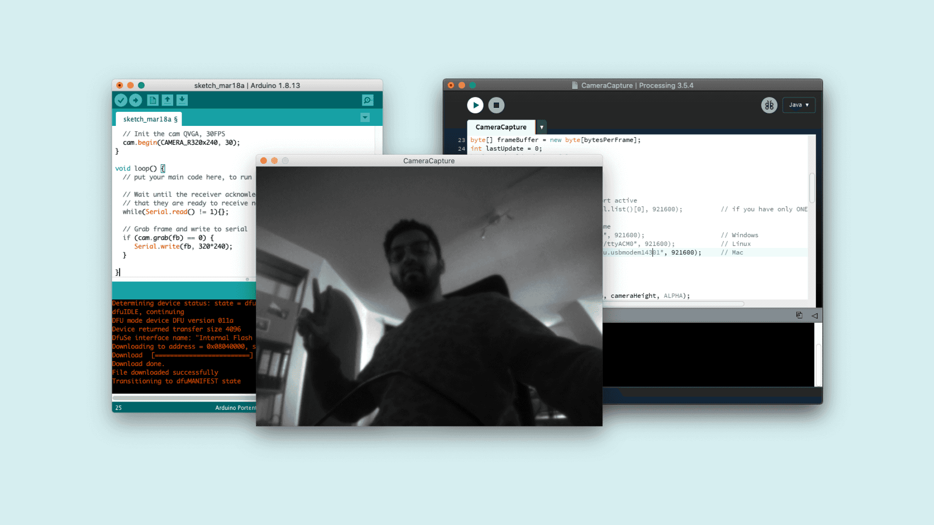
Conclusion
In this tutorial you learnt how to capture the frames from your Portenta Vision Shield's Camera and to visualize the frames through Processing. This knowledge can be useful for you to build and experiment simple computer vision applications for both outdoor and indoor environments.
Complete Sketch
The
CaptureRawBytes.ino1#include "camera.h"2#include "himax.h"3
4HM01B0 himax;5Camera cam(himax);6#define IMAGE_MODE CAMERA_GRAYSCALE7FrameBuffer fb(320,240,2);8
9unsigned long lastUpdate = 0;10
11void setup() {12 Serial.begin(921600);13 //Init the cam QVGA, 30FPS14 cam.begin(CAMERA_R320x240, IMAGE_MODE, 30);15}16
17void loop() {18 // put your main code here, to run repeatedly:19 if(!Serial) { 20 Serial.begin(921600);21 while(!Serial);22 }23 24 // Time out after 2 seconds and send new data25 bool timeoutDetected = millis() - lastUpdate > 2000;26
27 // Wait until the receiver acknowledges28 // that they are ready to receive new data29 if(!timeoutDetected && Serial.read() != 1) return;30
31 lastUpdate = millis();32 33 // Grab frame and write to serial34 if (cam.grabFrame(fb, 3000) == 0) {35 Serial.write(fb.getBuffer(), cam.frameSize());36 }37}The
CameraViewer.pde1/*2 This sketch reads a raw Stream of RGB565 pixels3 from the Serial port and displays the frame on4 the window.5 Use with the Examples -> CameraCaptureRawBytes Arduino sketch.6 This example code is in the public domain.7*/8
9import processing.serial.*;10import java.nio.ByteBuffer;11import java.nio.ByteOrder;12
13Serial myPort;14
15// must match resolution used in the sketch16final int cameraWidth = 320;17final int cameraHeight = 240;18final int cameraBytesPerPixel = 1;19final int cameraPixelCount = cameraWidth * cameraHeight;20final int bytesPerFrame = cameraPixelCount * cameraBytesPerPixel;21
22PImage myImage;23byte[] frameBuffer = new byte[bytesPerFrame];24int lastUpdate = 0;25boolean shouldRedraw = false;26
27void setup() {28 size(640, 480);29
30 // if you have only ONE serial port active31 //myPort = new Serial(this, Serial.list()[0], 921600); // if you have only ONE serial port active32
33 // if you know the serial port name34 //myPort = new Serial(this, "COM5", 921600); // Windows35 //myPort = new Serial(this, "/dev/ttyACM0", 921600); // Linux36 myPort = new Serial(this, "/dev/cu.usbmodem14401", 921600); // Mac37
38 // wait for full frame of bytes39 myPort.buffer(bytesPerFrame); 40
41 myImage = createImage(cameraWidth, cameraHeight, ALPHA);42 43 // Let the Arduino sketch know we're ready to receive data44 myPort.write(1);45}46
47void draw() {48 // Time out after 1.5 seconds and ask for new data49 if(millis() - lastUpdate > 1500) {50 println("Connection timed out.");51 myPort.clear();52 myPort.write(1);53 }54 55 if(shouldRedraw){ 56 PImage img = myImage.copy();57 img.resize(640, 480);58 image(img, 0, 0);59 shouldRedraw = false;60 }61}62
63void serialEvent(Serial myPort) {64 lastUpdate = millis();65 66 // read the received bytes67 myPort.readBytes(frameBuffer);68
69 // Access raw bytes via byte buffer 70 ByteBuffer bb = ByteBuffer.wrap(frameBuffer);71 72 /* 73 Ensure proper endianness of the data for > 8 bit values.74 When using > 8bit values uncomment the following line and75 adjust the translation to the pixel color. 76 */ 77 //bb.order(ByteOrder.BIG_ENDIAN);78
79 int i = 0;80
81 while (bb.hasRemaining()) {82 // read 8-bit pixel83 byte pixelValue = bb.get();84
85 // set pixel color86 myImage.pixels[i++] = color(Byte.toUnsignedInt(pixelValue)); 87 }88 89 myImage.updatePixels();90 91 // Ensures that the new image data is drawn in the next draw loop92 shouldRedraw = true;93 94 // Let the Arduino sketch know we received all pixels95 // and are ready for the next frame96 myPort.write(1);97}Suggest changes
The content on docs.arduino.cc is facilitated through a public GitHub repository. If you see anything wrong, you can edit this page here.
License
The Arduino documentation is licensed under the Creative Commons Attribution-Share Alike 4.0 license.