Portenta Max Carrier User Manual
Get a general overview of Portenta Max Carrier and its features.
Overview
This user manual offers a detailed guide on the Portenta Max Carrier, consolidating all its features for easy reference. It will show how to set up, adjust, and assess its main functionalities. This document will enable any user to proficiently operate the Portenta Max Carrier, making it suitable for project developments related to industrial automation, manufacturing automation, robotics, and prototyping.
Hardware and Software Requirements
Hardware Requirements
- Portenta Max Carrier (x1)
- Portenta X8 (x1)
- Portenta C33 (x1)
- Portenta H7 (x1)
- USB-C® cable (either USB-C® to USB-A or USB-C® to USB-C®) (x1)
- Wi-Fi® Access Point or Ethernet with Internet access (x1)
Software Requirements
Product Overview
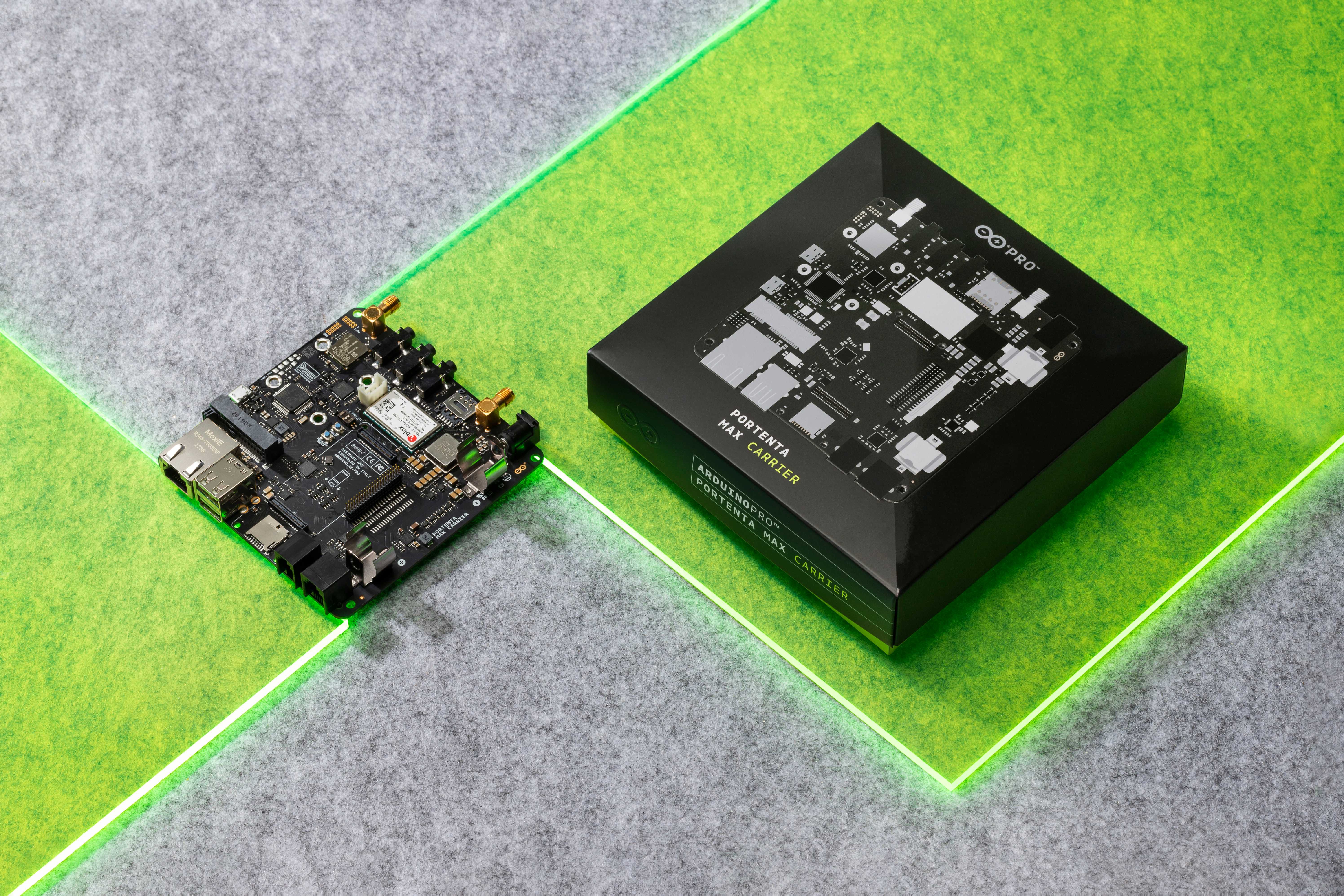
Max Carrier transforms Portenta modules into single-board computers with edge AI capabilities for high-performance industrial, building automation and robotics applications. Thanks to its dedicated high-density connectors, Portenta Max Carrier can be paired with Portenta X8, H7, or C33, allowing any user to easily prototype and deploy multiple industrial projects.
This Arduino Pro carrier further augments Portenta connectivity options with Fieldbus, LoRa®, Cat-M1 and NB-IoT. Among the many available plug-and-play connectors, there are Gigabit Ethernet, USB-A, audio jacks, microSD, mini-PCIe, MIPI camera, FD-CAN, and Serial RS-232/422/485. Max Carrier can be powered via external supply (6-36V) or battery via the onboard 18650 Li-ion battery connector.
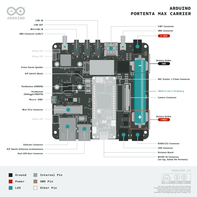
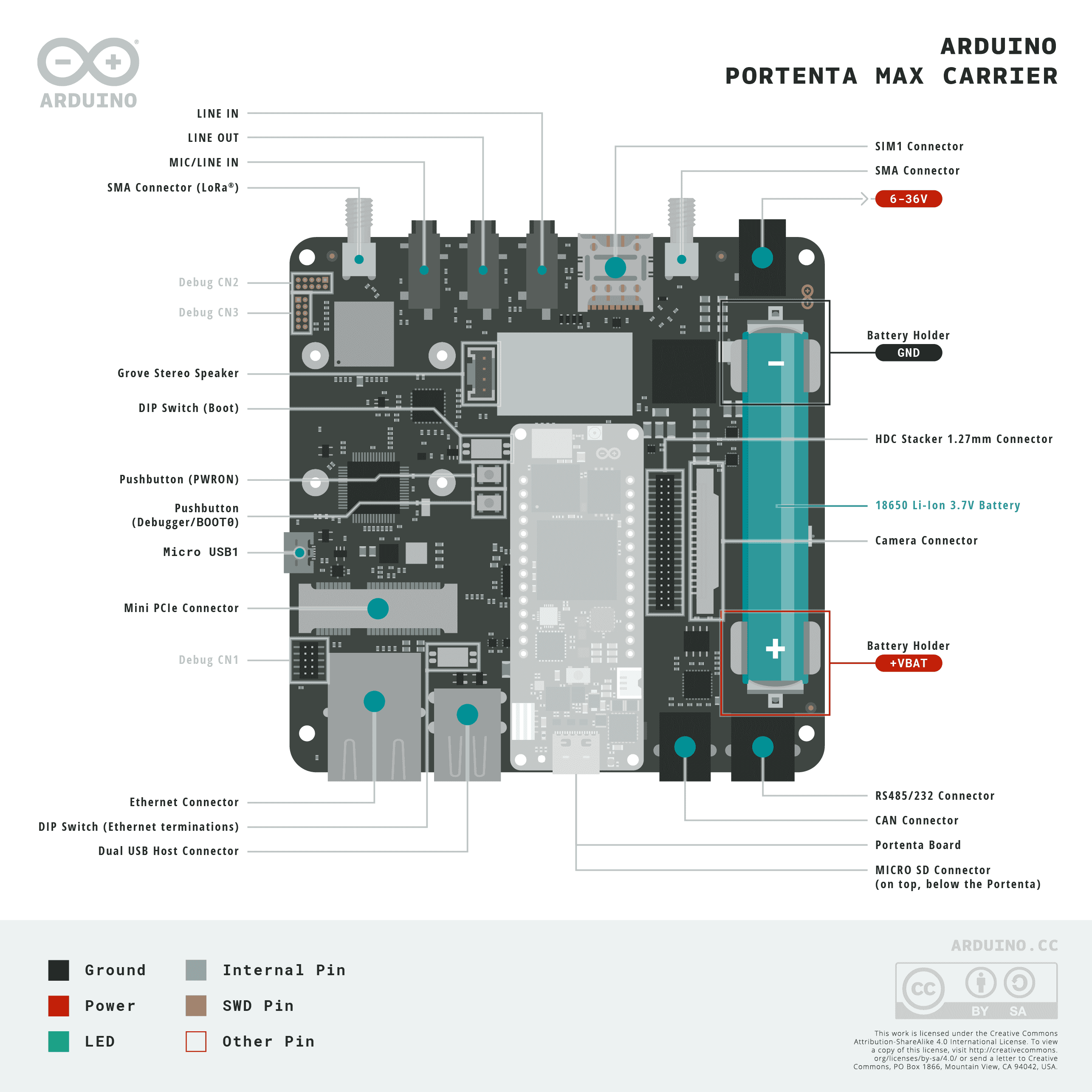
Carrier Architecture Overview
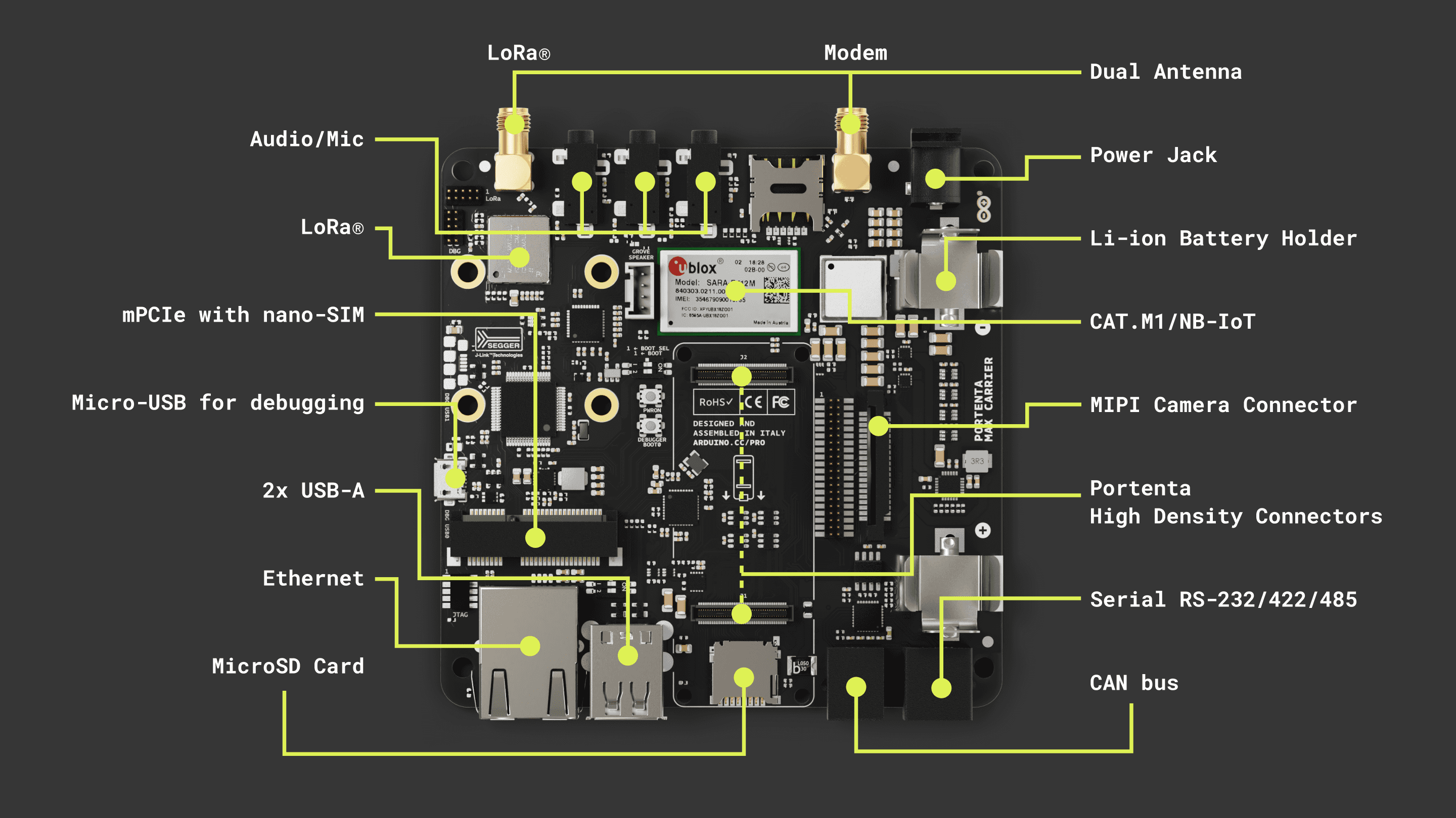
Here is an overview of the board's architecture's main components shown in the image above:
Compatible core: The board is compatible with Portenta X8 (ABX00049), Portenta H7 (ABX00042/ABX00045/ABX00046), and Portenta C33 (ABX00074). The Portenta H7 and C33 are limited in camera support and the Ethernet speed to 100 Mbit.
Power management: The Portenta Max Carrier can either be powered through the power jack (6 ~ 36V DC) or an 18650 Li-ion/LiPo battery (3.7V), which can be used as a backup power source if the external power supply fails. The battery is charged when the minimum input voltage to the power jack is met.
USB connectivity: The Portenta Max Carrier also includes a USB 2.0 High-Speed Hub controller based on the USB2514B/M2 that manages the 2 USB devices of the USB type A connector plus the LoRa® and PCIe modules. J15 is protected by an NCP383LMUAJAATXG power switch and current limiter.
A USB-A female connector can be used for data logging and the connection of external peripherals like keyboards, mice, hubs, and similar devices.
Ethernet connectivity: The Gigabit Ethernet physical interface (J17) is directly connected to the high density connector to the Portenta board. The connector includes an activity LED indication (orange) and speed indication (green). Note: Gigabit Ethernet functionality is only supported on the Portenta X8. Portenta H7 and Portenta C33 just support 100 Mbit Ethernet speed.
Serial Transceiver: The Portenta Max Carrier includes a multi-protocol transceiver supporting RS-232, RS-485, and RS-422 serial standards (configurable) based on the SP335 IC. It is connected to a 6P6C Connector (RJ11, RJ12, RJ14, RJ25).
CAN Transceiver: The Portenta Max Carrier includes a high speed CAN transceiver based on the TJA1049T/3J IC. It is connected to a 4P4C connector (RJ9, RJ10, RJ22).
Mini PCIe: The Portenta Max Carrier includes one female mini PCI Express card slot. The connector is right angled and the board includes 2 removable standoffs for external module support. The Max Carrier supports two different Mini PCIe sizes. Pins 8, 10, 12 and 14 are reserved for UIM (in this case SIM). Note: USB, I2C and SIM functionality over PCIe is available only for the X8.
Cellular Modem: The SARA-R412M-02B is a multi-region modem capable of connecting to 2G/Cat-M1/NB-IoT networks worldwide. A dedicated SMA connector is provided for connecting an external antenna. The chip operates over the 1V8 power line. A microSIM slot is available, the corresponding SIM card slot for the cell modem is on the top side of the board, directly adjacent to the module.
Audio: The Portenta Max Carrier enables connections to analog audio channels. This is done through the low power CS42L52 stereo CODEC providing ADC/DAC between analog signals and the I2S protocol. An internal Class D amplifier eliminates the need for external audio amplification circuitry.
LoRa® Module: The Portenta Max Carrier provides long range wireless connectivity for low bandwidth applications with the onboard Murata CMWX1ZZABZ-078 LoRa® transceiver module. This module operates at 3V3. A dedicated SMA connector is provided for connecting an external antenna.
MIPI Camera: The Portenta Max Carrier, when combined with a Portenta X8, supports MIPI cameras. The latter can be plugged into the onboard camera connector (J4) via a flexible flat cable. The camera support is perfect for machine/computer vision applications such as product line inspection, object detection, image classification and robotics.
Storage: The board has a MicroSD card slot for data logging operation.
Debug interface: Debugging capabilities are integrated directly into the Portenta Max Carrier and are accessible via micro USB. The J-link debugger is compatible with the Segger® J-Link OB and Blackmagic probes, driven by the STM32F405RGT6 controller. In addition to providing access to the Portenta board JTAG ports, different sniffer channels for I2C, CAN and UART lines are available. The debugger firmware can be updated via SWD on CN3. Additionally, headers for debugging the LoRa® are accessible via CN2 with SWD.
DIP switch: The carrier has a DIP switch with two positions and enables different profiles depending on the paired Portenta board. See the DIP Switches section for more details.
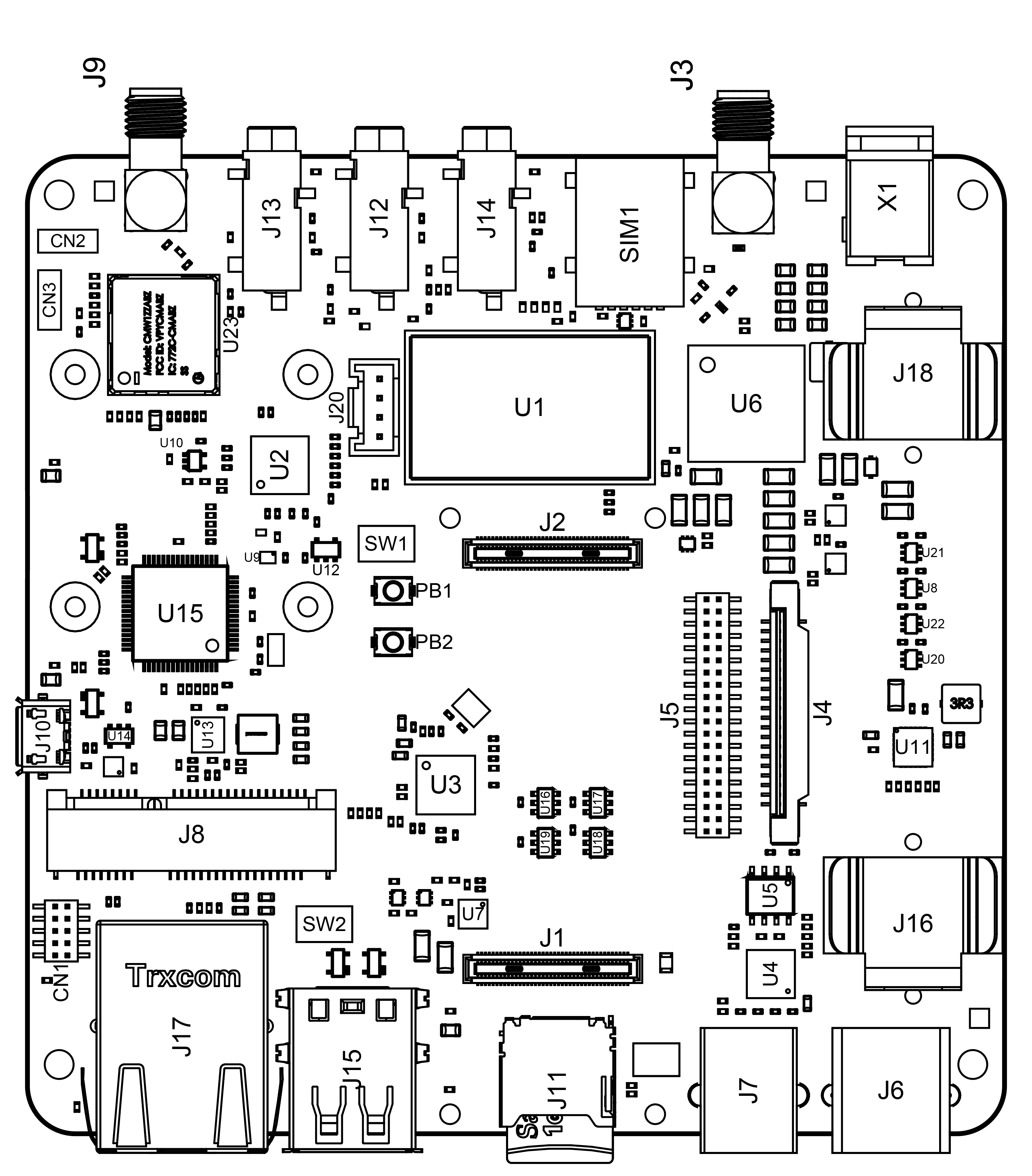
Carrier Topology
| Ref. | Description | Ref. | Description |
|---|---|---|---|
| U1 | SARA-R412M-02B 4G LTE/Cat-M1/NB-IoT Modem IC | U2 | CS42L52-CNZ Stereo Codec IC |
| U3 | USB2514Bi/M2 4-port USB 2.0 Hub IC | U4 | SP335EER1-L RS232/RS485/RS422 Transceiver IC |
| U5 | TJA1049 CAN Transceiver IC | U6 | MPM3550EGLE Non-isolated DC-DC IC |
| U7 | NCP383 Current Limiting IC | U8,U20,U21,U22 | SN74LVC1T45 Bi-directional logic level converter IC |
| U9 | DSC6111HI2B 12MHz MEMS Oscillator IC | U10 | SN74LVC1G125 Single Bus Buffer Gate IC |
| U11 | BQ24195RGET 4.5A Single Cell Charger IC | U12 | AP7311 1.8V 150mA LDO Linear Regulator IC |
| U13 | TPS54620 6A Buck Regulator IC | U14 | AP2112K-3.3TRG1 3.3V 600mA LDO Regulator IC |
| U15 | STM32F405RG 168MHz 32 bit Arm® Cortex®-M4 MCU IC | U16-U19 | 74LVC1G157 Single 2-input multiplexer IC |
| U23 | CMWX1ZZABZ-078 Murrata LoRa® module | U24, U25 | LM73100 Ideal Diode with Reverse Polarity Protection |
| J1, J2 | DF40HC(3.5)-80DS-0.4V(51) High Density Connectors | J3 | Right-Angle SMA Connector for Modem |
| J4 | Camera 2-1734248-0 FPC Connector | J5 | FW-20-05-G-D-254-150 Signal Break |
| J6 | 615006138421 RS232/RS485 Connector | J7 | 615006138421 CAN Connector |
| J8 | 1759546-1 Mini PCIe Connector | J9 | Right-Angle SMA Connector for LoRa® |
| J10 | ZX62-AB-5PA(31) Micro USB Debugger Connector with VBUS | J11 | 114-00841-68 Micro SD Connector |
| J12 | SJ-3524-SMT-TR 3.5mm Headphone Out | J13 | SJ-3524-SMT-TR 3.5mm Line In Right |
| J14 | SJ-3524-SMT-TR 3.5mm Line In Left | J15 | 61400826021 2-port USB 2.0 Female Connector |
| J16 | 254TR Positive Li-ion Terminal | J17 | TRJK7003A97NL Gigabit Ethernet Connector |
| J18 | 254TR Negative Li-ion Terminal | ||
| J20 | 110990030 Connector for Speaker | X1 | PJ-102A 5.5mm Power Jack Adapter |
| CN1 | FTSH-105-01-F-DV 10-pin JTAG Header | CN2 | Debug Header |
| CN3 | LoRa® Debug Header | SIM1 | 2199337-5 microSIM Card Holder (for on-board modem) |
| SW1 | 218-2LPST Boot Select Switch | SW2 | 218-2LPST Switch (2) |
| PB1 | PTS820J25KSMTRLFS Power On Button | PB2 | PTS820J25KSMTRLFS Reset Button |
Carrier Characteristics Highlight
The Portenta Max Carrier extends the features of the Portenta X8, H7, and C33. The following table summarizes the carrier's characteristics depending on the paired Portenta.
| Function | Portenta H7/C33 Support | Portenta X8 Support | Notes |
|---|---|---|---|
| USB Host | USB 1.0 | USB 2.0 | Max Speed: USB 1.0 - 12 Mbps, USB 2.0 - 480 Mbps |
| Ethernet | 100 Mbps | 1 Gbps | |
| CAN | Portenta C33 only | Yes | |
| Mini PCIe (USB) | USB 1.0 | USB 2.0 | Max Speed: USB 1.0 - 12 Mbps, USB 2.0 - 480 Mbps |
| Mini PCIe (PCIe) | No | PCIe 2.0 | |
| Battery Charger | Yes | Yes | |
| LoRa® | Yes | Yes | |
| NBIoT/CatM1/2G | Yes | Yes | |
| Camera | No | MIPI up to 4 lanes | No MIPI camera support on H7/C33 |
| Audio | Limited | Yes | No firmware support for the H7 |
| RS232/422/485 | Yes | Yes | |
| on board JTAG debugging | Yes | No | |
| on board console to USB | Yes | Yes | |
| on board bus sniffing | Limited | Limited | Only hardware support |
The table above provides a general idea of how the Portenta Max Carrier performs depending on the paired Portenta board. Each feature is explained in the following section after a quick guide covering how to properly interface the Portenta boards.
Pinout
Portenta Max Carrier Pinout
The full pinout is available and downloadable as PDF from the link below:
Datasheet
The full datasheet is available and downloadable as PDF from the link below:
Schematics
The full schematics are available and downloadable as PDF from the link below:
STEP Files
The full STEP files are available and downloadable from the link below:
Altium Files
The full Altium files are available and downloadable from the link below:
First Use
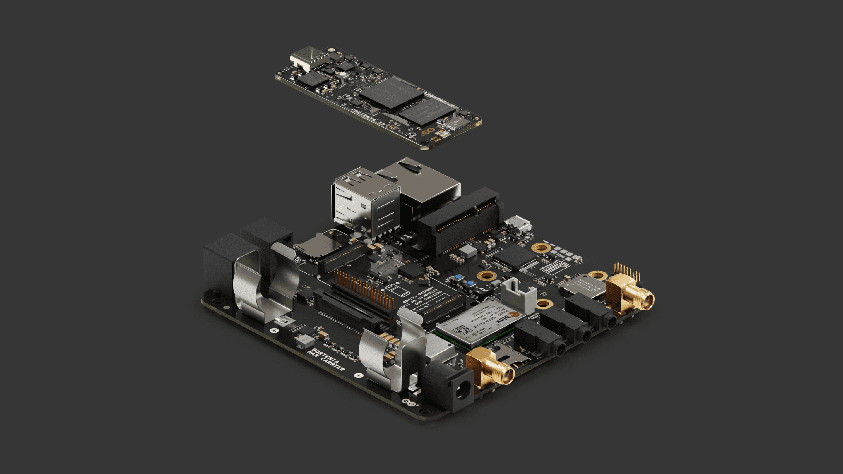
Stack The Carrier
The Portenta Max Carrier design enables an easy stack of the preferred Portenta board. The following figure shows how the Portenta boards pair via the High-Density connectors.
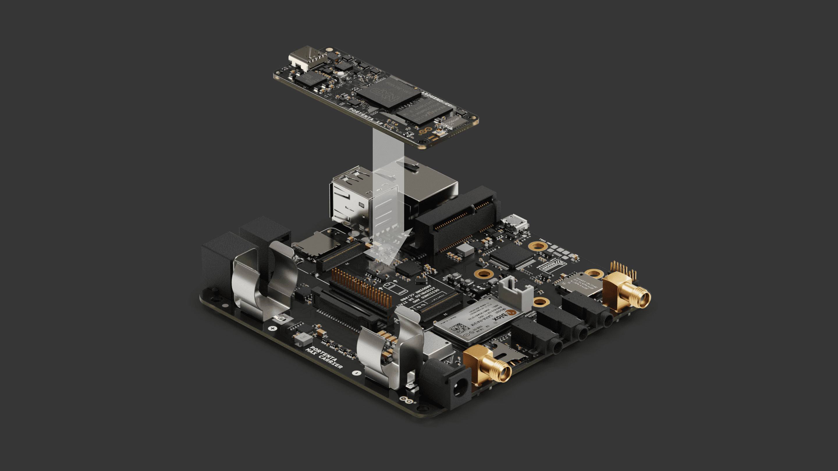
With the Portenta mounted to the carrier, you can proceed to power the carrier and begin prototyping.
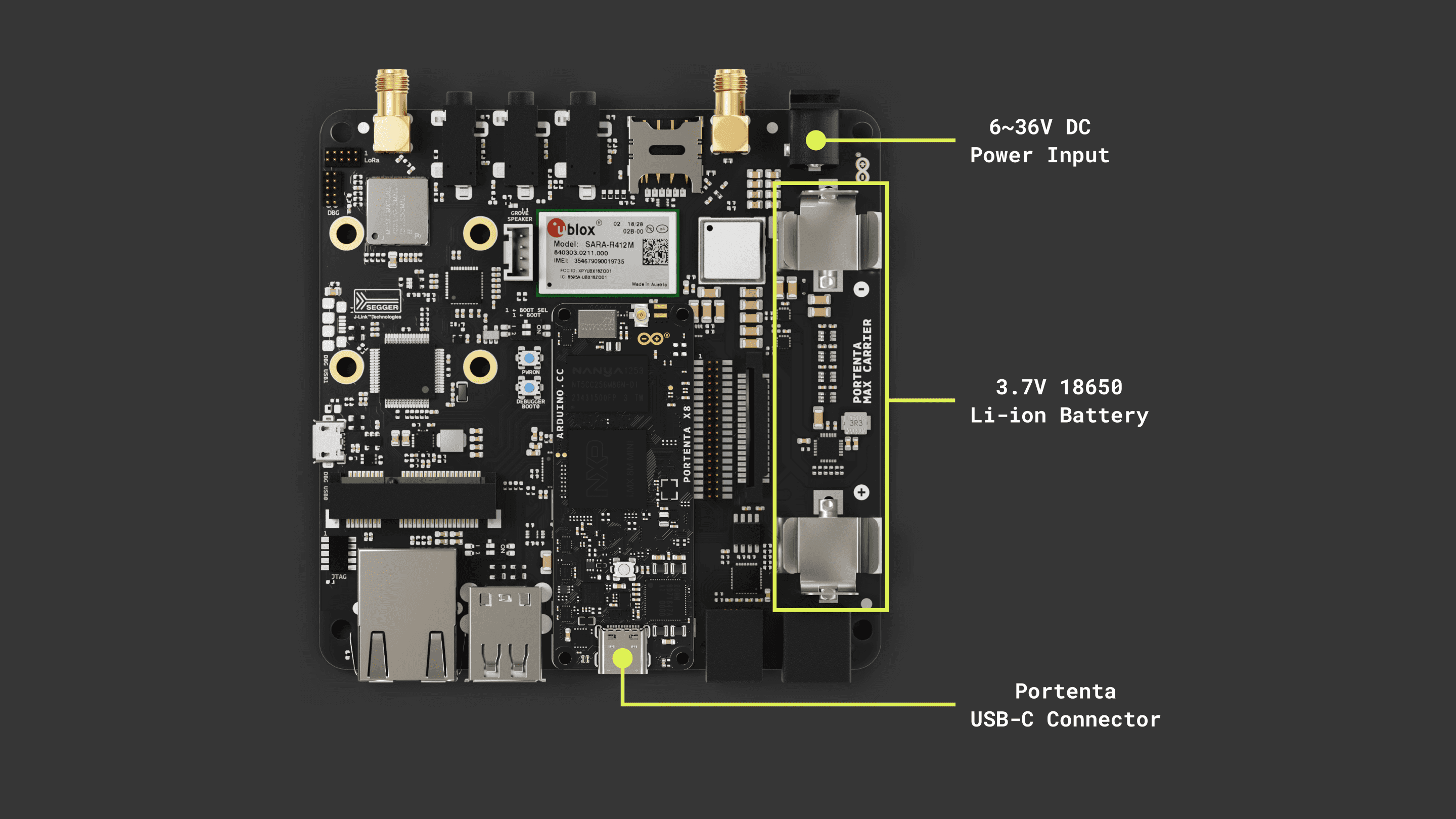
Power The Board
The Portenta Max Carrier can be powered using the following methods:
- Using an external 6 to 36V power supply connected to the
of the board.Power Jack - Using a 3.7V 18650 Li-ion battery inserted in the on-board battery socket.
- Using a USB-C® cable connected to the Portenta core board of your choice. (This option does not power the Modem and Mini PCIe connector).
Please ensure to connect the battery with the right polarity, not doing so may damage the board.
Hello World
Let's test the Portenta Max Carrier with the classic
Hello WorldBlinkTo configure the Ethernet settings, depending on the paired Portenta board, you must properly set the provided DIP switch located on the Portenta Max Carrier.
The Portenta Max Carrier incorporates two DIP switches, giving users the ability to manage the behavior of the board. The configuration parameters of these switches differ based on which Portenta board it is paired with.
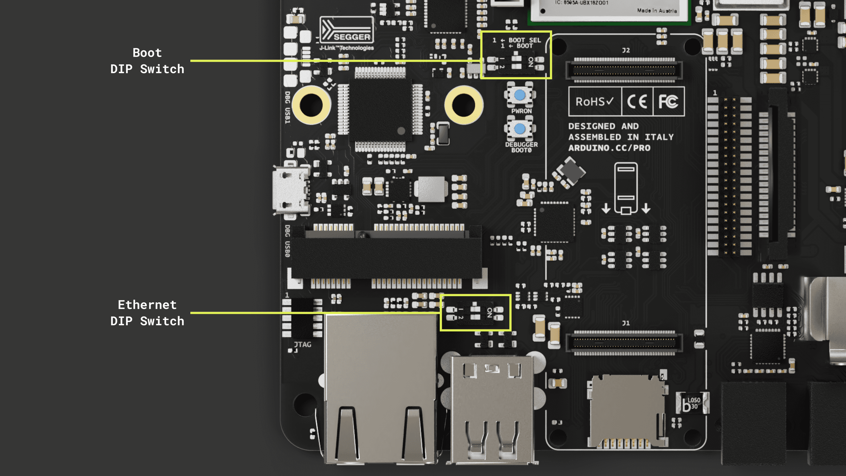
For configurations when the Portenta Max Carrier is combined with the Portenta boards, the DIP switch governs these settings:
| Ethernet DIP Switch Designation | Position: ON | Position: OFF |
|---|---|---|
| 1 - 2 | Ethernet Disabled for X8 / Enabled for H7/C33 | Ethernet Enabled for X8 / Disabled for H7/C33 |
For an in-depth understanding of the DIP switch, kindly refer to this section.
Using Linux
For the Portenta X8, be sure the ethernet DIP switches are both set to OFF. Then connect the board using a LAN cable to the network.
Enter to your Portenta X8 using
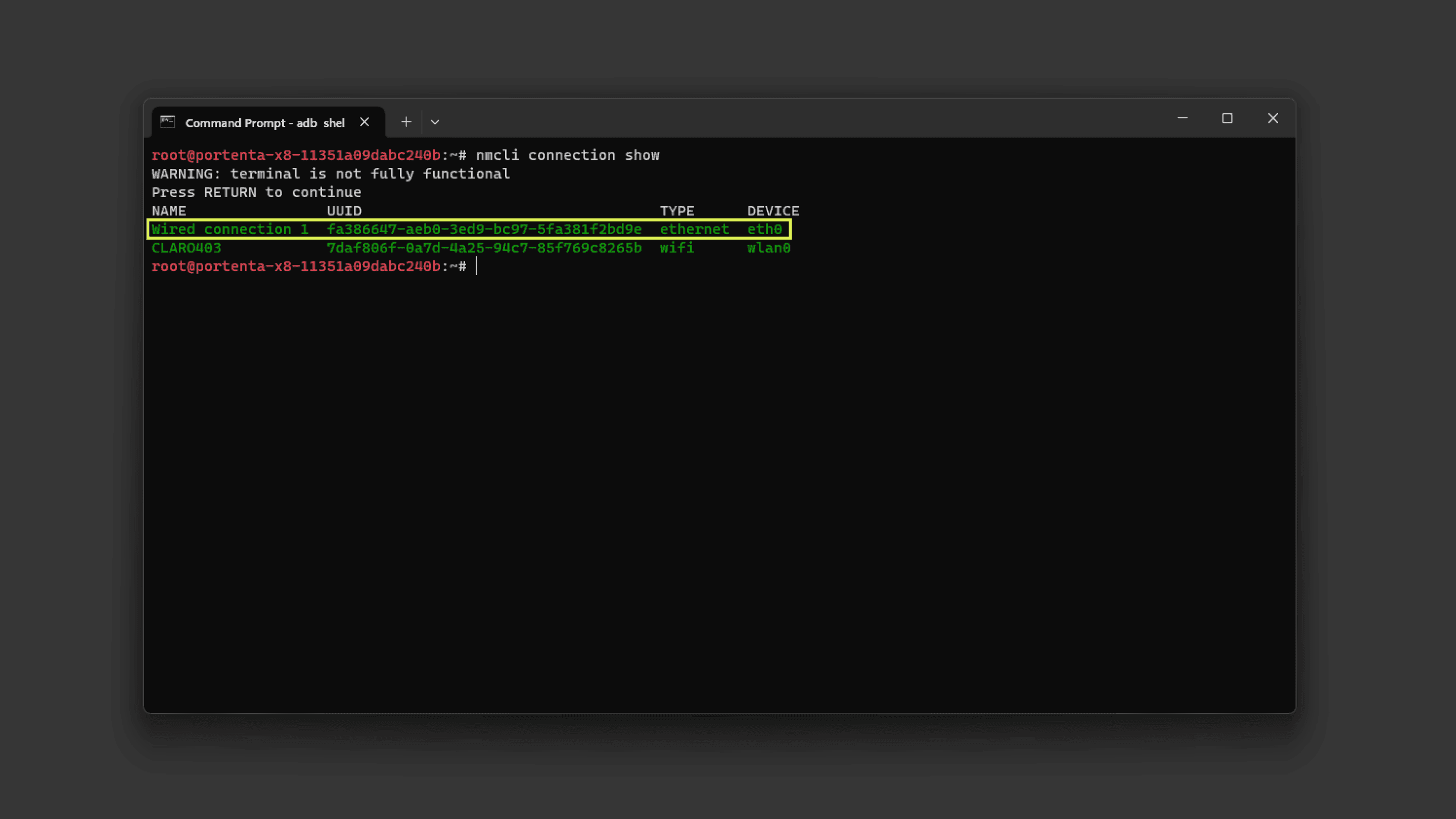
adb shellsudo su -fioFirst, you need an internet connection to download the tool. You can establish one using the following commands:
1nmcli connection show # To find the ethernet device name ("eth0" in this case)If your ethernet connection is up and running you should see something similar to this:
If not, you can create a DHCP network with a custom name and interface with the following commands:
1nmcli conn add con-name <NtwrkName> type ethernet ifname <DevName> ipv4.method auto # Create a DHCP network. <NtwrkName> will be the custom network alias and <DevName> must be the device name found with the past command.2
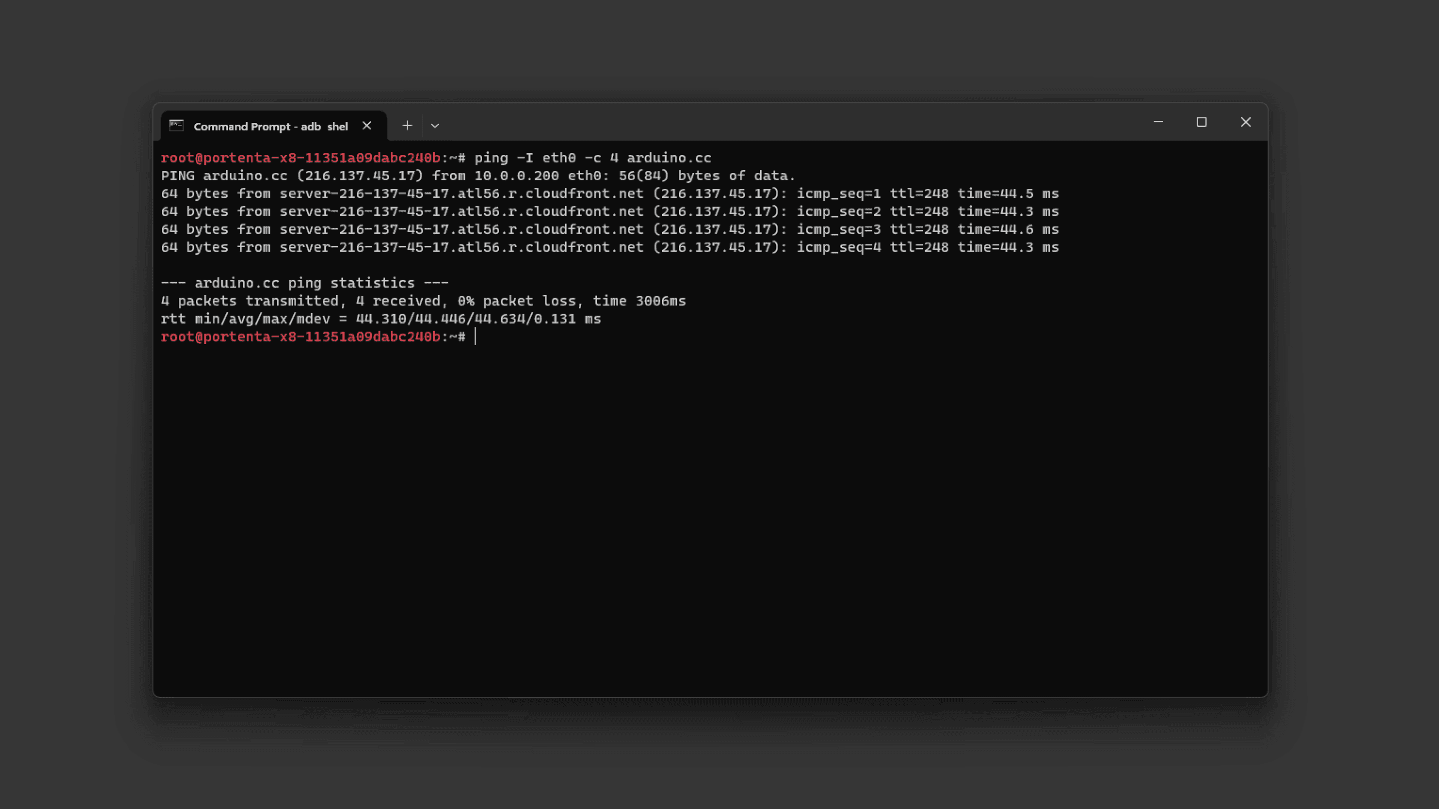
3nmcli conn up <NtwrkName> # Initiate the connectionTo test if we are successfully connected, let's make a
ping1ping -I eth0 -c 4 arduino.cc # ping 4 times to Arduino's webpage using ethernetIf you have a working ethernet connection to the internet, the ping should show the latency as follows:
Using Arduino IDE
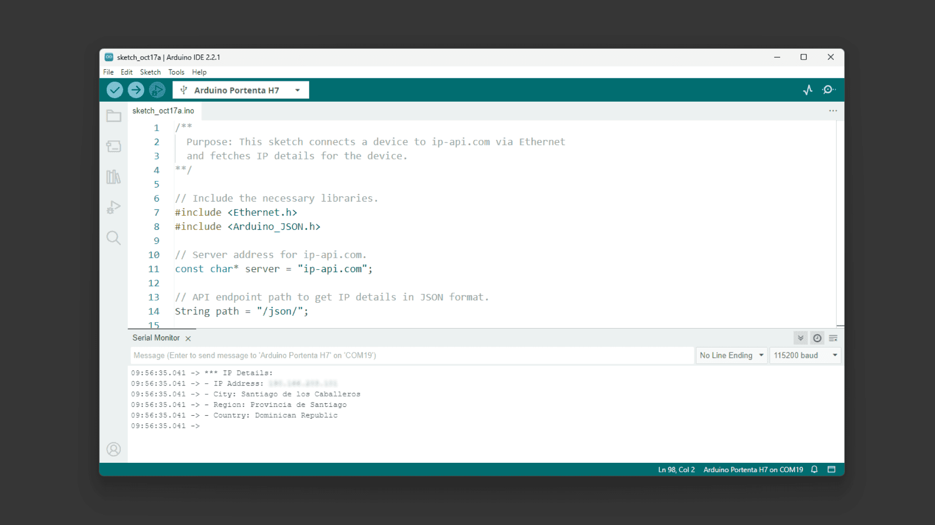
To test the Ethernet connection using a Portenta H7 or a Portenta C33 we are going to use an example sketch that will retrieve your City information from the internet and show it through the Serial Monitor.
When using the Portenta H7 or the Portenta C33, be sure the ethernet DIP switches are both set to ON. Then connect the board using a LAN cable to the network.
1/**2 Purpose: This sketch connects a device to ip-api.com via Ethernet3 and fetches IP details for the device.4**/5
6// Include the necessary libraries.7#if defined(ARDUINO_PORTENTA_H7_M7)8 #include <PortentaEthernet.h> // for Portenta H7 9#elif defined(ARDUINO_PORTENTA_C33)10 #include <EthernetC33.h> // for Portenta C3311#endif12
13#include <Arduino_JSON.h>14
15// Server address for ip-api.com.16const char* server = "ip-api.com";17
18// API endpoint path to get IP details in JSON format.19String path = "/json/";20
21// Ethernet client instance for the communication.22EthernetClient client;23
24// JSON variable to store and process the fetched data.25JSONVar doc;26
27// Variable to ensure we fetch data only once.28bool dataFetched = false;29
30void setup() {31 // Begin serial communication at a baud rate of 115200.32 Serial.begin(115200);33
34 // Wait for the serial port to connect,35 // This is necessary for boards that have native USB.36 while (!Serial);37
38 // Attempt to start Ethernet connection via DHCP,39 // If DHCP failed, print a diagnostic message.40 if (Ethernet.begin() == 0) {41 Serial.println("- Failed to configure Ethernet using DHCP!");42
43 }44 printIPAddress();45 delay(2000);46}47
48void loop() {49 // Ensure we haven't fetched data already,50 // ensure the Ethernet link is active,51 // establish a connection to the server,52 // compose and send the HTTP GET request.53 if (!dataFetched) {54 if (Ethernet.linkStatus() == LinkON) {55 if (client.connect(server, 80)) {56 client.print("GET ");57 client.print(path);58 client.println(" HTTP/1.1");59 client.print("Host: ");60 client.println(server);61 client.println("Connection: close");62 client.println();63
64 // Wait and skip the HTTP headers to get to the JSON data.65 char endOfHeaders[] = "\r\n\r\n";66 client.find(endOfHeaders);67
68 // Read and parse the JSON response.69 String payload = client.readString();70 doc = JSON.parse(payload);71
72 // Check if the parsing was successful.73 if (JSON.typeof(doc) == "undefined") {74 Serial.println("- Parsing failed!");75 return;76 }77
78 // Extract and print the IP details.79 Serial.println("*** IP Details:");80 Serial.print("- IP Address: ");81 Serial.println((const char*)doc["query"]);82 Serial.print("- City: ");83 Serial.println((const char*)doc["city"]);84 Serial.print("- Region: ");85 Serial.println((const char*)doc["regionName"]);86 Serial.print("- Country: ");87 Serial.println((const char*)doc["country"]);88 Serial.println("");89
90 // Mark data as fetched.91 dataFetched = true;92 }93 // Close the client connection once done.94 client.stop();95 } else {96 Serial.println("- Ethernet link disconnected!");97 }98 }99}100
101void printIPAddress()102{103 Serial.print("Connected to: ");104 for (byte thisByte = 0; thisByte < 4; thisByte++) {105 // print the value of each byte of the IP address:106 Serial.print(Ethernet.localIP()[thisByte], DEC);107 Serial.print(".");108 }109
110 Serial.println();111}If the connection is successful, you should see your IP address and location information printed out in the Arduino IDE Serial Monitor.
High-Density Connectors
The Portenta X8, H7, and C33 enhance functionality through High-Density connectors. For a comprehensive understanding of these connectors, please refer to the complete pinout documentation for each Portenta model.
- Complete Portenta X8 pinout information
- Complete Portenta H7 pinout information
- Complete Portenta C33 pinout information
Configuration and Control
Configuration and control features enable the customization of the device's behavior to its specific needs. Whether you would like to set up network connectivity or adjust switch configurations, this sub-section will guide you through the carrier connectivity and profile setup processes.
DIP Switch Configuration
The Portenta Max Carrier incorporates two DIP switches, giving users the ability to manage the behavior of the board. The configuration parameters of these switches differ based on which Portenta board it is paired with.
For configurations when the Portenta Max Carrier is combined with the Portenta boards, the DIP switch governs these settings:
| Ethernet DIP Switch Designation | Position: ON | Position: OFF |
|---|---|---|
| 1 - 2 | Ethernet Disabled for X8 / Enabled for H7/C33 | Ethernet Enabled for X8 / Enabled for H7/C33 |
| Boot DIP Switch Designation | Position: ON | Position: OFF |
|---|---|---|
| BOOT SEL | Enter Boot Mode for X8 / Not used for H7/C33 | Normal boot from Portenta onboard memory for X8 / Not used for H7/C33 |
| BOOT | Not officially supported for X8 / Enter Boot mode for H7/C33 | Boot from MMC Memory for X8 / Normal Boot (Run) for H7/C33 |
This flexibility ensures that the Portenta Max Carrier remains adaptable to the unique needs of each paired Portenta board.
Learn more about how the different DIP Switches configurations work and help you to flash images to the Portenta X8 following this guide.
Network Connectivity
Ethernet
The Portenta Max Carrier is equipped with an Ethernet interface, specifically an RJ45 connector supporting 1000 Base-T.
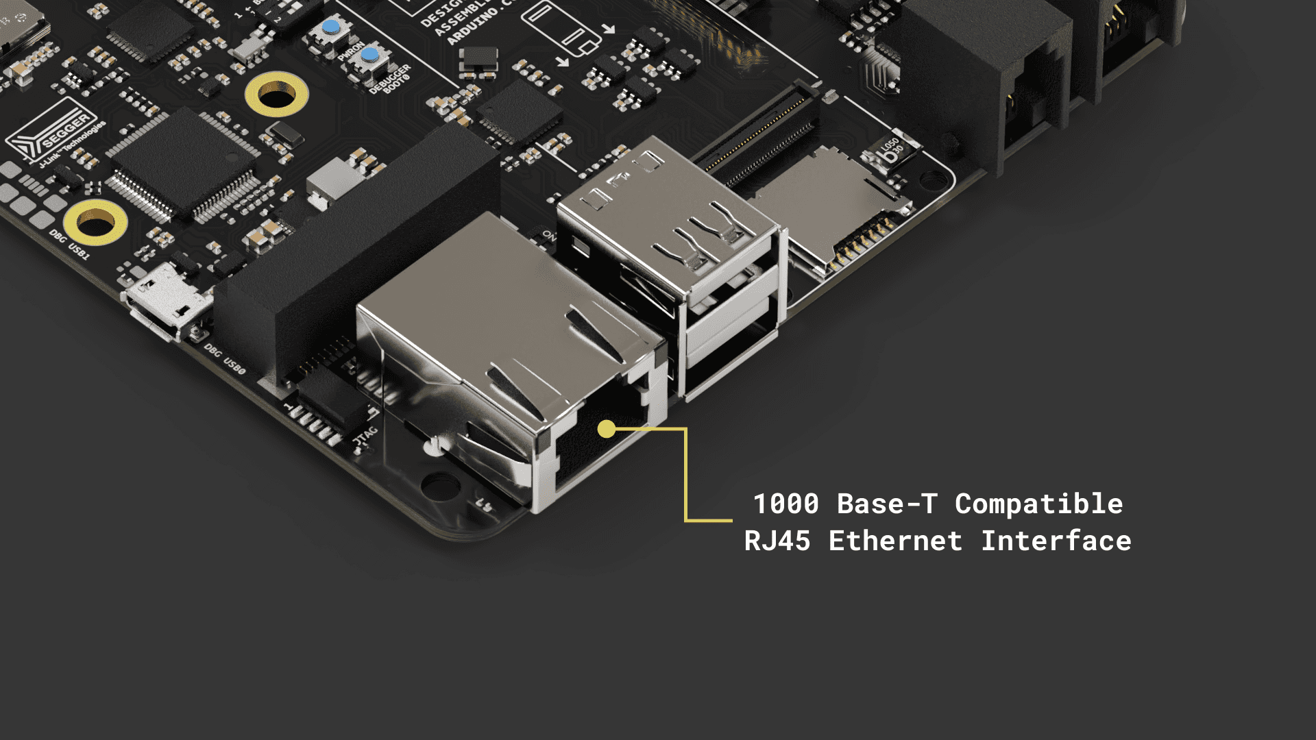
Ethernet performance differs based on the associated Portenta board:
- With the Portenta X8: The system supports 1 Gbit Ethernet.
- When combined with the Portenta H7 or C33: The performance is limited to 100 Mbit Ethernet.
To configure the Ethernet settings, depending on the paired Portenta board, you must properly set the provided DIP switch located on the Portenta Max Carrier. For an in-depth understanding of the DIP switch, kindly refer to this section.
Using Linux
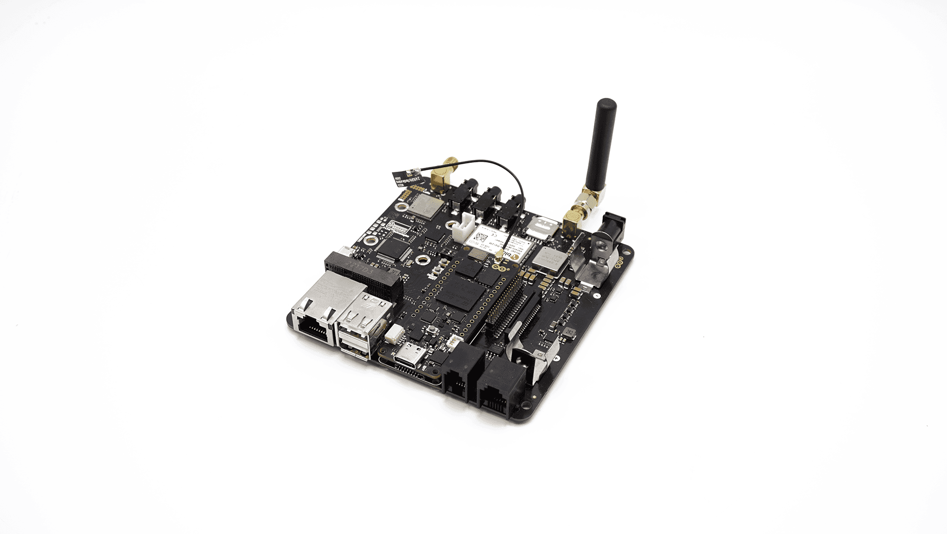
Using the Portenta X8 in combination with the Max Carrier allows you to evaluate the Ethernet speed. First, ensure the Portenta X8 is mounted on the Max Carrier, and then connect them using a LAN cable.
To measure the bandwidth, use the
iperf3Enter to your Portenta X8 using
adb shellsudo su -fioFirst, you need an internet connection to download the tool. You can establish one using the following commands:
1nmcli connection show # To find the ethernet device name ("eth0" in this case)If your ethernet connection is up and running you should see something similar to this:
If not, you can create a DHCP network with a custom name and interface with the following commands:
1nmcli conn add con-name <NtwrkName> type ethernet ifname <DevName> ipv4.method auto # Create a DHCP network. <NtwrkName> will be the custom network alias and <DevName> must be the device name found with the past command.2
3nmcli conn up <NtwrkName> # Initiate the connectionTo test if we are successfully connected, let's make a
ping1ping -I eth0 -c 4 arduino.cc # ping 4 times to Arduino's webpage using ethernetIf you have a working internet connection, the ping should show the latency as follows:
Now we know we are connected through ethernet, let's do the speed test. To install the
iperf31mkdir -p ~/bin && source ~/.profile2wget -qO ~/bin/iperf3 https://github.com/userdocs/iperf3-static/releases/latest/download/iperf3-arm64v83chmod 700 ~/bin/iperf3To verify the installation, type
~/bin/iperf3 -v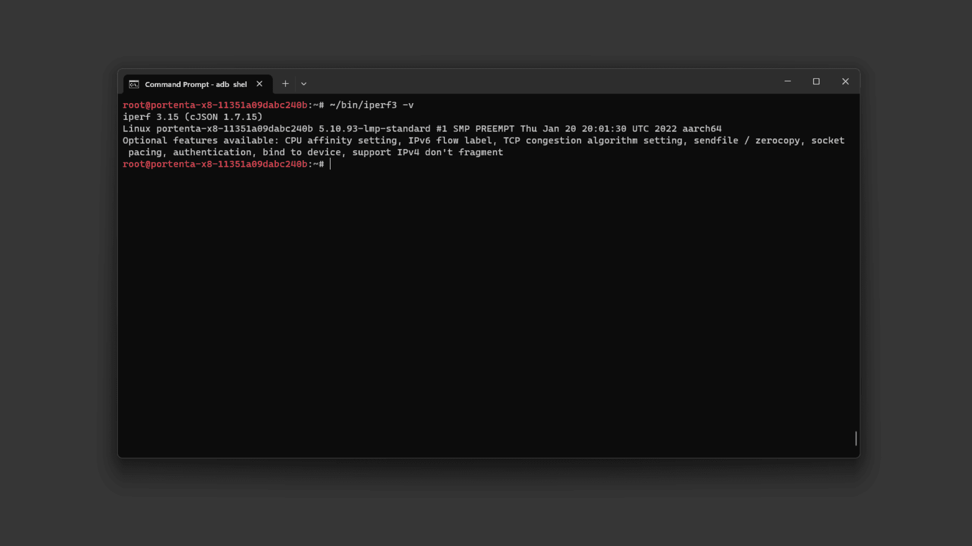
As the speed test must be done between two devices to measure the link speed, we need to install
iperf3Once installed on both devices, we should set one as a
serverclient1~/bin/iperf3 -s # run this on the Portenta X8 (Server)1iperf3.exe -c <Server IP Address> # run this on your PC (Windows) from the iperf3 download directory and use the Portenta X8 IP address.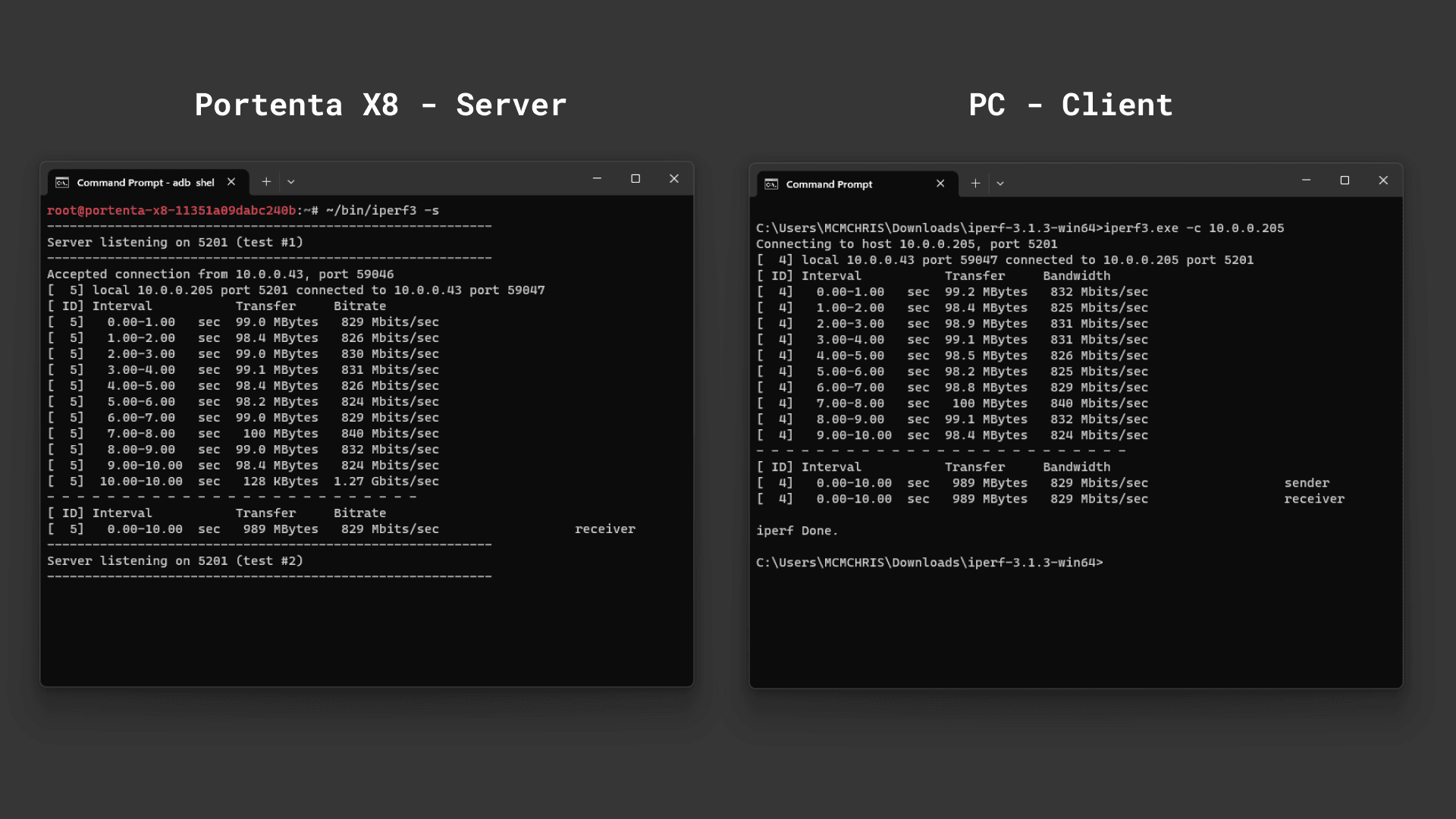
The speed results could be affected by your Ethernet cable quality or your PC Ethernet card.
Using Arduino IDE
To test the Ethernet connection using a Portenta H7 or a Portenta C33 we are going to use an example sketch that will retrieve your City information from the internet and show it through the Serial Monitor.
1/**2 Purpose: This sketch connects a device to ip-api.com via Ethernet3 and fetches IP details for the device.4**/5
6// Include the necessary libraries.7#if defined(ARDUINO_PORTENTA_H7_M7)8 #include <PortentaEthernet.h> // for Portenta H7 9#elif defined(ARDUINO_PORTENTA_C33)10 #include <EthernetC33.h> // for Portenta C3311#endif12
13#include <Arduino_JSON.h>14
15// Server address for ip-api.com.16const char* server = "ip-api.com";17
18// API endpoint path to get IP details in JSON format.19String path = "/json/";20
21// Ethernet client instance for the communication.22EthernetClient client;23
24// JSON variable to store and process the fetched data.25JSONVar doc;26
27// Variable to ensure we fetch data only once.28bool dataFetched = false;29
30void setup() {31 // Begin serial communication at a baud rate of 115200.32 Serial.begin(115200);33
34 // Wait for the serial port to connect,35 // This is necessary for boards that have native USB.36 while (!Serial);37
38 // Attempt to start Ethernet connection via DHCP,39 // If DHCP failed, print a diagnostic message.40 if (Ethernet.begin() == 0) {41 Serial.println("- Failed to configure Ethernet using DHCP!");42
43 }44 printIPAddress();45 delay(2000);46}47
48void loop() {49 // Ensure we haven't fetched data already,50 // ensure the Ethernet link is active,51 // establish a connection to the server,52 // compose and send the HTTP GET request.53 if (!dataFetched) {54 if (Ethernet.linkStatus() == LinkON) {55 if (client.connect(server, 80)) {56 client.print("GET ");57 client.print(path);58 client.println(" HTTP/1.1");59 client.print("Host: ");60 client.println(server);61 client.println("Connection: close");62 client.println();63
64 // Wait and skip the HTTP headers to get to the JSON data.65 char endOfHeaders[] = "\r\n\r\n";66 client.find(endOfHeaders);67
68 // Read and parse the JSON response.69 String payload = client.readString();70 doc = JSON.parse(payload);71
72 // Check if the parsing was successful.73 if (JSON.typeof(doc) == "undefined") {74 Serial.println("- Parsing failed!");75 return;76 }77
78 // Extract and print the IP details.79 Serial.println("*** IP Details:");80 Serial.print("- IP Address: ");81 Serial.println((const char*)doc["query"]);82 Serial.print("- City: ");83 Serial.println((const char*)doc["city"]);84 Serial.print("- Region: ");85 Serial.println((const char*)doc["regionName"]);86 Serial.print("- Country: ");87 Serial.println((const char*)doc["country"]);88 Serial.println("");89
90 // Mark data as fetched.91 dataFetched = true;92 }93 // Close the client connection once done.94 client.stop();95 } else {96 Serial.println("- Ethernet link disconnected!");97 }98 }99}100
101void printIPAddress()102{103 Serial.print("Connected to: ");104 for (byte thisByte = 0; thisByte < 4; thisByte++) {105 // print the value of each byte of the IP address:106 Serial.print(Ethernet.localIP()[thisByte], DEC);107 Serial.print(".");108 }109
110 Serial.println();111}
Wi-Fi® & Bluetooth®
The Portenta Max Carrier is designed to work flawlessly with wireless features. Among its numerous advantages is its capacity to use Wi-Fi® and Bluetooth® technologies present in the Portenta models like X8, H7, or C33. When these wireless options are activated, they can be effectively combined with the intrinsic capabilities and features that the carrier offers. This combination makes this solution more versatile and powerful for many different projects.
This integration not only broadens the spectrum of use cases for the Portenta Max Carrier but also ensures that developers can use robust wireless communications in their applications. The effectiveness of onboard capabilities with these wireless features makes the Portenta Max Carrier an indispensable tool for developers looking for versatile and powerful connectivity solutions.
For a comprehensive understanding of these connectivity options, kindly refer to the specific documentation for each Portenta model.
- Portenta X8 connectivity: Wi-Fi® configuration and Bluetooth®
- Portenta H7 connectivity: Wi-Fi® access point and BLE connectivity
- Portenta C33 User Manual: Wi-Fi® and Bluetooth®
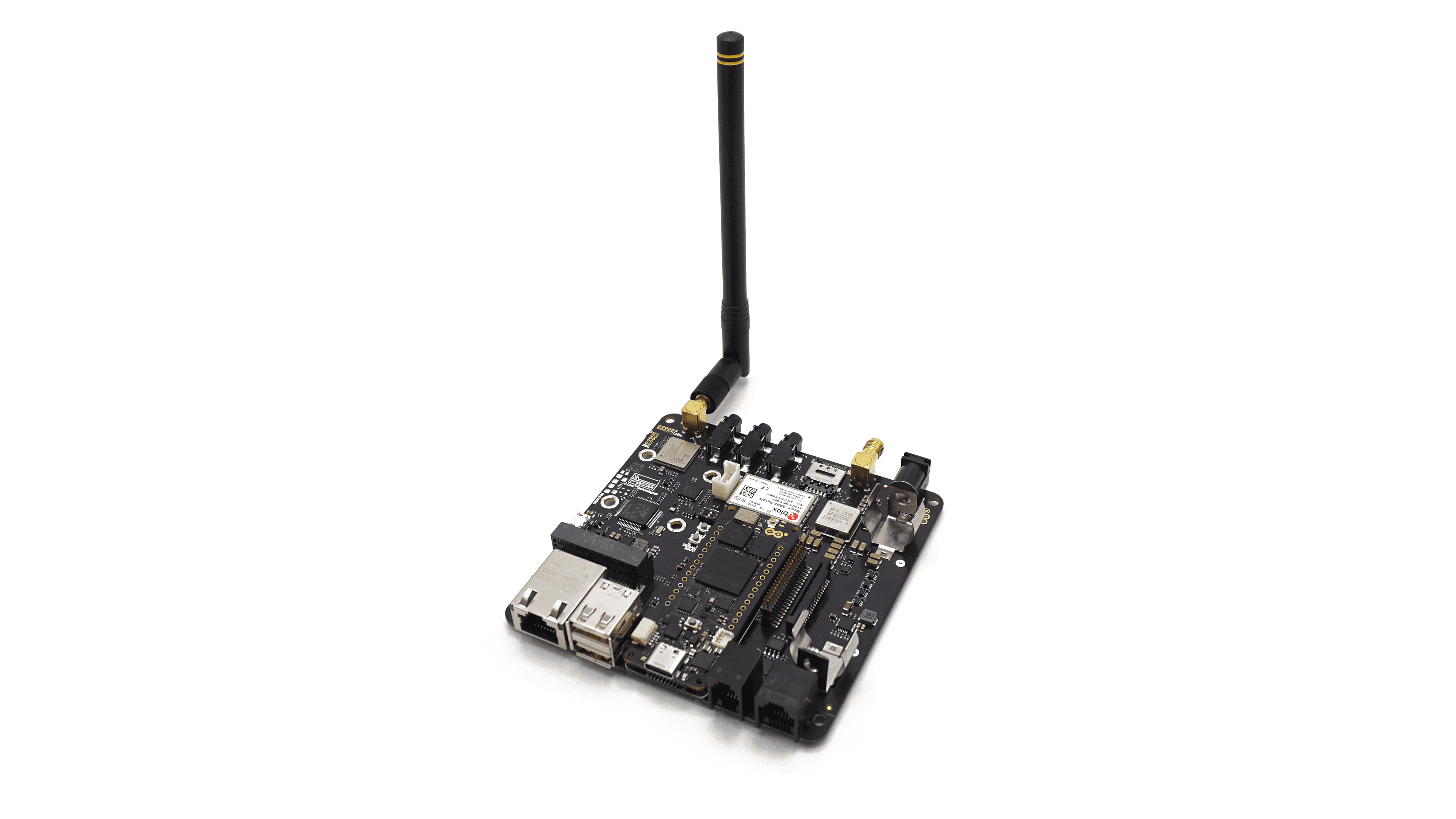
LTE CAT.M1 NB-IoT
To ensure connectivity in a wide variety of possible scenarios, the Max Carrier features cellular connectivity powered by the SARA-R412M-02B multi-band module.
You can easily connect your solution to the internet leveraging the more suitable communication protocol, from LTE, NB-IoT, Cat.M1 and more.
Recommended cellular antenna: ANT-5GW-SPS1-2
Using Arduino IDE
To use the cellular connectivity we are going to use a Portenta H7 alongside the Max Carrier. To drive the module we recommend the
MKRNBTo quickly find out if the setup successfully connects to mobile networks, we are going to use an example code that can be found on File > Examples > MKRNB > NBWwebClient.
Go to the arduino_secrets.h tab that opens with the example and enter the PIN of the SIM card you are using into the
SECRET_PINNUMBERNote: A standard pre-paid SIM card typically has 0000 or 1234 as a PIN code. This varies from operator to operator, it is important to find out your PIN before uploading the code. Otherwise, too many unsuccessful attempts may block the SIM card.
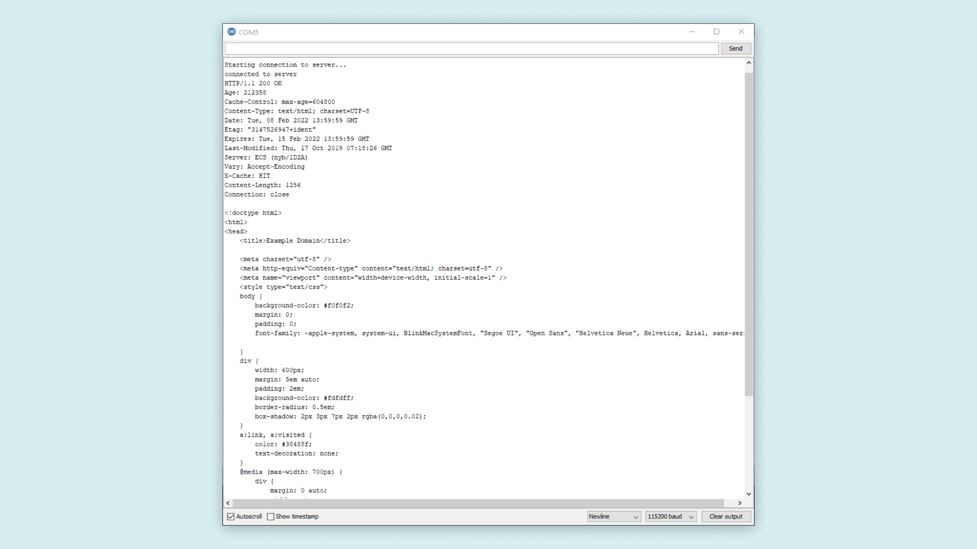
Upload the code to your Portenta H7 and open the Serial Monitor to follow the connection process.
If the connection is successful, you should see the HTML content of the server printed in the Serial Monitor. The server is set as
example.comBelow you can see what will be printed in the Serial Monitor when connecting to example.com.
LoRa®
One feature that boosts Portenta Max Carrier possibilities is its onboard LoRa® module, the CMWX1ZZABZ-078 from Murata®. LoRaWAN® is a Low Power Wide Area Network (LPWAN) protocol designed to connect low-power devices to the Internet. It has been developed to meet and fulfill Internet of Things (IoT) devices' requirements, such as low power consumption and low data throughput.
A dedicated SMA connector (J9) is available for connecting an external antenna.
Recommended LoRa® antenna: ANT-8/9-IPW1-SMA
Using Linux
Empower your Portenta X8 connectivity with LoRa® by following this detailed guide on How to set up a multi-protocol gateway using the Portenta X8 and the Max Carrier
Using Arduino IDE
To learn how to leverage LoRa® capabilities with this carrier and the Arduino IDE, follow this detailed tutorial on How to Connect the Portenta Max Carrier with The Things Network using a Portenta H7
Audio Interface
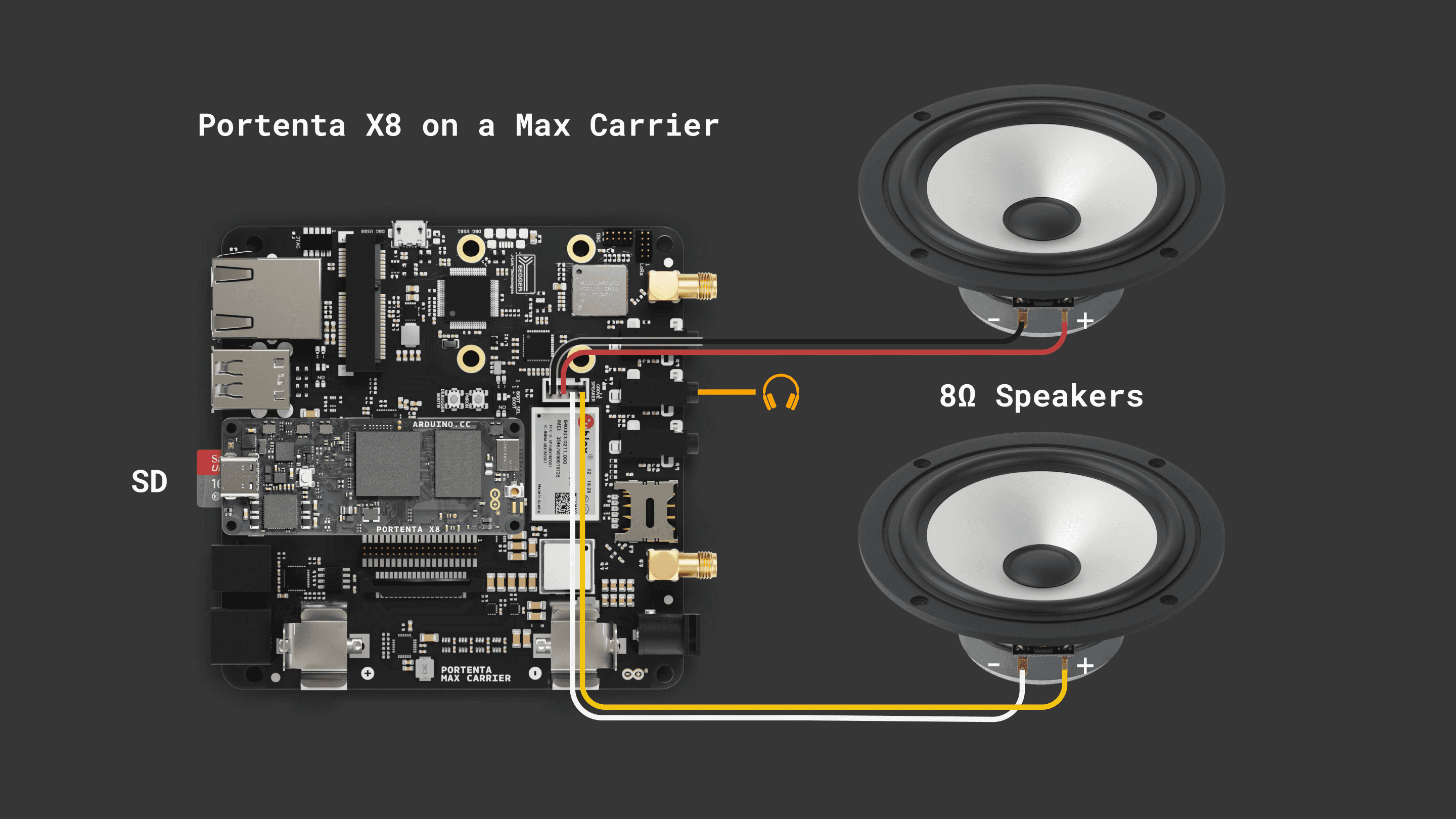
The Portenta Max Carrier features a low-power but mighty stereo CODEC, ideal for audio applications powered by the Portenta X8. An internal Class D amplifier lets us play high-quality audio directly on external speakers.
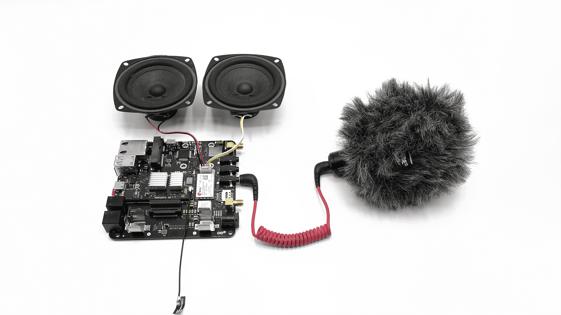
The audio recording couldn't be simpler thanks to its variety of audio inputs, letting you connect a microphone or any other audio source.
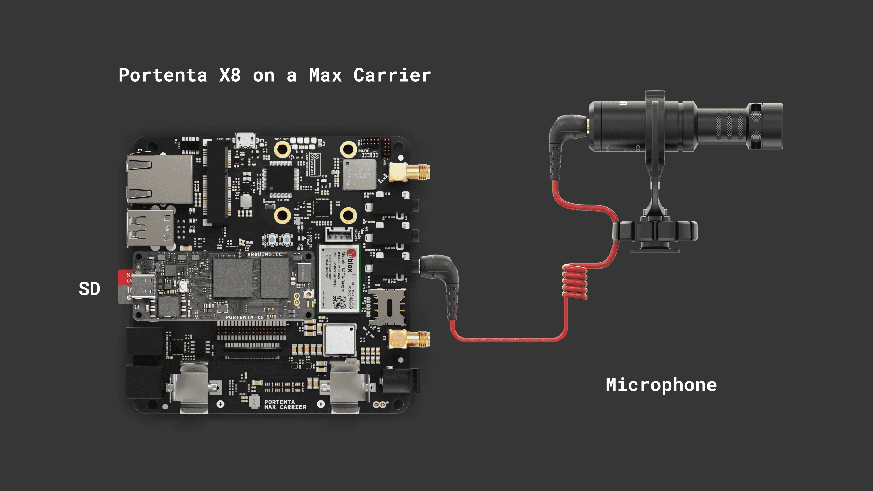
Recording Audio
In the following example, we are going to record audio using an external microphone and store it on a micro SD card.
First of all, let's connect to the internet to download the tools and run the needed Docker containers.
Use
to easily connect to a WiFi network.nmcli device wifi connect <SSID> password <PASSWORD>
After inserting the micro SD in the Max Carrier slot, mount it with the following command.
1sudo mount -t vfat /dev/mmcblk1p1 /mntRun the docker image
debian:stable-slim1docker run -it -u '0' --device '/dev/snd:/dev/snd' -v '/mnt:/sdcard' --tmpfs /tmp --name "alsa-utils" debian:stable-slim bashInstall the audio management tools. This procedure will take a while.
1apt-get update && apt-get install alsa-utils ffmpeg -yDefine the microphone inputs as the audio sources and the input gain.
1amixer -c 1 sset 'ADC Left Mux' 'Input3A' # Mic Input2amixer -c 1 sset 'ADC Right Mux' 'Input3B' # Mic Input3amixer -c 1 sset 'ADC' 100% # Mic volumeNow, we are ready for the audio recording. Use
ffmpegThe following command will record audio for 30 seconds at 44100 Hz and save it on
/sdcard/out.wav1ffmpeg -f alsa -i hw:1 -t 30 -ac 1 -ar 44100 -c:a pcm_s16le /sdcard/out.wavIf you want to learn more about the
tool and its options, here is a useful reference.ffmpeg
If we list the
/sdcard/ls /scard/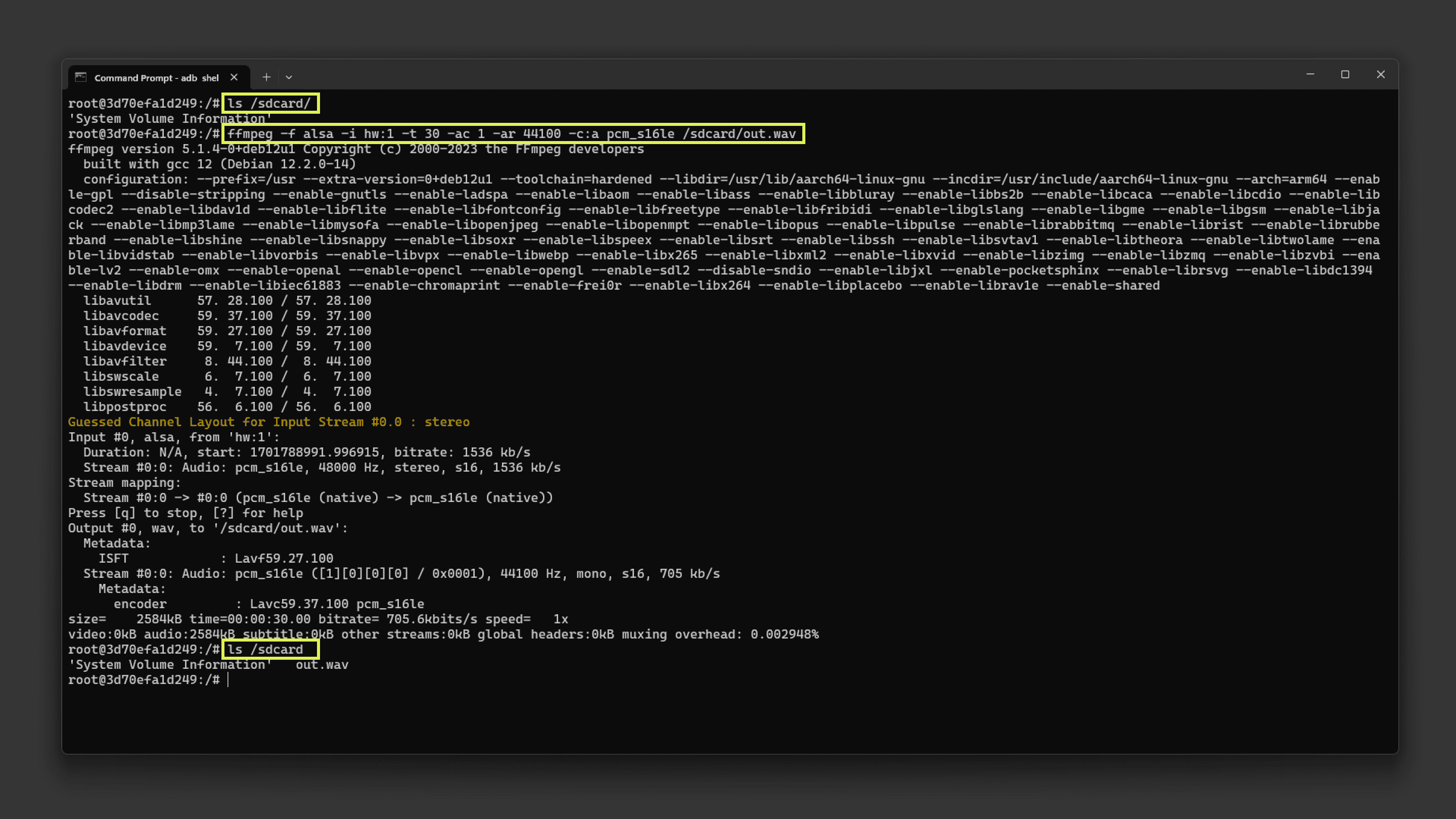
You can open the audio file on your computer by copying it with the following commands:
- First, find the
container ID withalsa-utils
.docker ps -a - Copy the file from the container to the X8 local storage with
sudo docker cp <CONTAINER ID>:/sdcard/out.wav /home/fio - The audio file is now on
, from here you can pull it using/home/fio
from a terminal. Useadbadb pull /home/fio/out.wav <destination path>
Playing Back Audio
In the following example, we are going to playback the previously recorded audio file and learn how to test the Max Carrier audio outputs.
First, it is important to know some commands to control the audio volume.
1# This sets the master output volume 2amixer -c 1 sset 'Master' 100% # accepts also a dB parameter 100% = 12dB3# This sets the headphone output volume 4amixer -c 1 sset 'Headphone' 0dB # 0dB = 100%5# This sets the speaker output volume 6amixer -c 1 sset 'Speaker' 100% # 100% = 0dBBy default, the Class D amplifier outputs are turned off. To play audio on the external speakers, you must turn them on with the following commands.
1amixer -c 1 sset 'SPK Right Amp' on # turn on the right channel speaker2amixer -c 1 sset 'SPK Left Amp' on # turn on the right channel speakerThe following command will play an example
.wav/usr/share/sounds/alsa1speaker-test -c 2 -D hw:cs42l52audio -t wavTo play a sine wave at 440 Hz, use:
1speaker-test -c 2 -D hw:cs42l52audio -t sine -f 440To play the recorded
.wav1aplay -c 2 -D hw:cs42l52audio -t wav /sdcard/out2.wavTo send a file from the Portenta X8 local storage to the container use: sudo docker cp /home/fio/<file>.wav <CONTAINER ID>:/sdcard
USB Interface
The Portenta Max Carrier features a USB interface suitable for data logging and connecting external devices.

If you are interested in the USB-A port pinout, the following table may serve to understand its connection distribution:
| Pin number | Power Net | Portenta HD Standard Pin | High-Density Pin | Interface |
|---|---|---|---|---|
| 1 | +5V | USB0_VBUS | J1-24 | |
| 2 | USB0_D_N | J1-28 | USB D- | |
| 3 | USB0_D_P | J1-26 | USB D+ | |
| 4 | GND | GND | J1-22, J1-31, J1-42, J1-47, J1-54, J2-24, J2-33, J2-44, J2-57, J2-70 |
Devices with a USB-A interface, such as storage drives, can be used for logging data. External devices include peripherals like keyboards, mouses, webcams, and hubs.
Using Linux
As an example, the following command on Portenta X8's shell can be used to test a write command with a USB memory drive. To write a file, the following sequence of commands can help you to accomplish such a task.
1sudo su -First of all, let's enter root mode to have the right permissions to mount and unmount related peripherals like our USB memory drive.
1lsblkThe
lsblk/dev/sda1lsblklsusb1mkdir -p /mnt/USBmountThe
mkdir -p/mnt/USBmount1mount -t vfat /dev/sda1 /mnt/USBmountThis mount command mounts the USB drive, assumed to have a FAT filesystem (
vfat/dev/sda1/mnt/USBmount/mnt/USBmountcd1cd /mnt/USBmountNow if you do an
ls1ls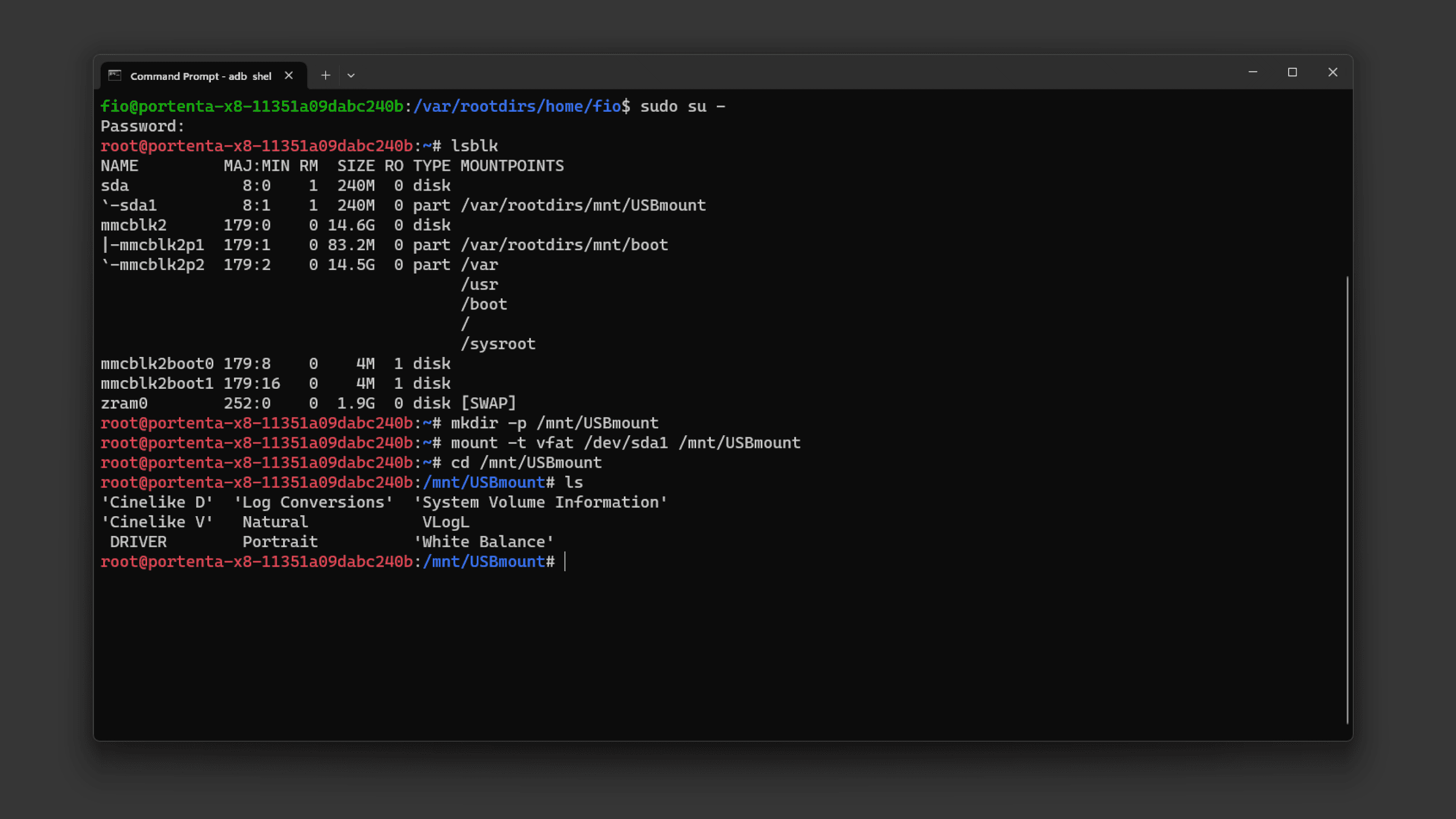
Let's create a simple text file containing the message
Hello, World!1dd if=<(echo -n "Hello, World!") of=/mnt/USBmount/helloworld.txtThis command uses the
ddechoHello, World!ddSubsequently, the message gets inscribed into a file named helloworld.txt situated in the
/mnt/USBmountAfter creating the file, if you wish to retrieve its contents and display them on the shell, you can use:
1cat helloworld.txtThis command
catHello, World!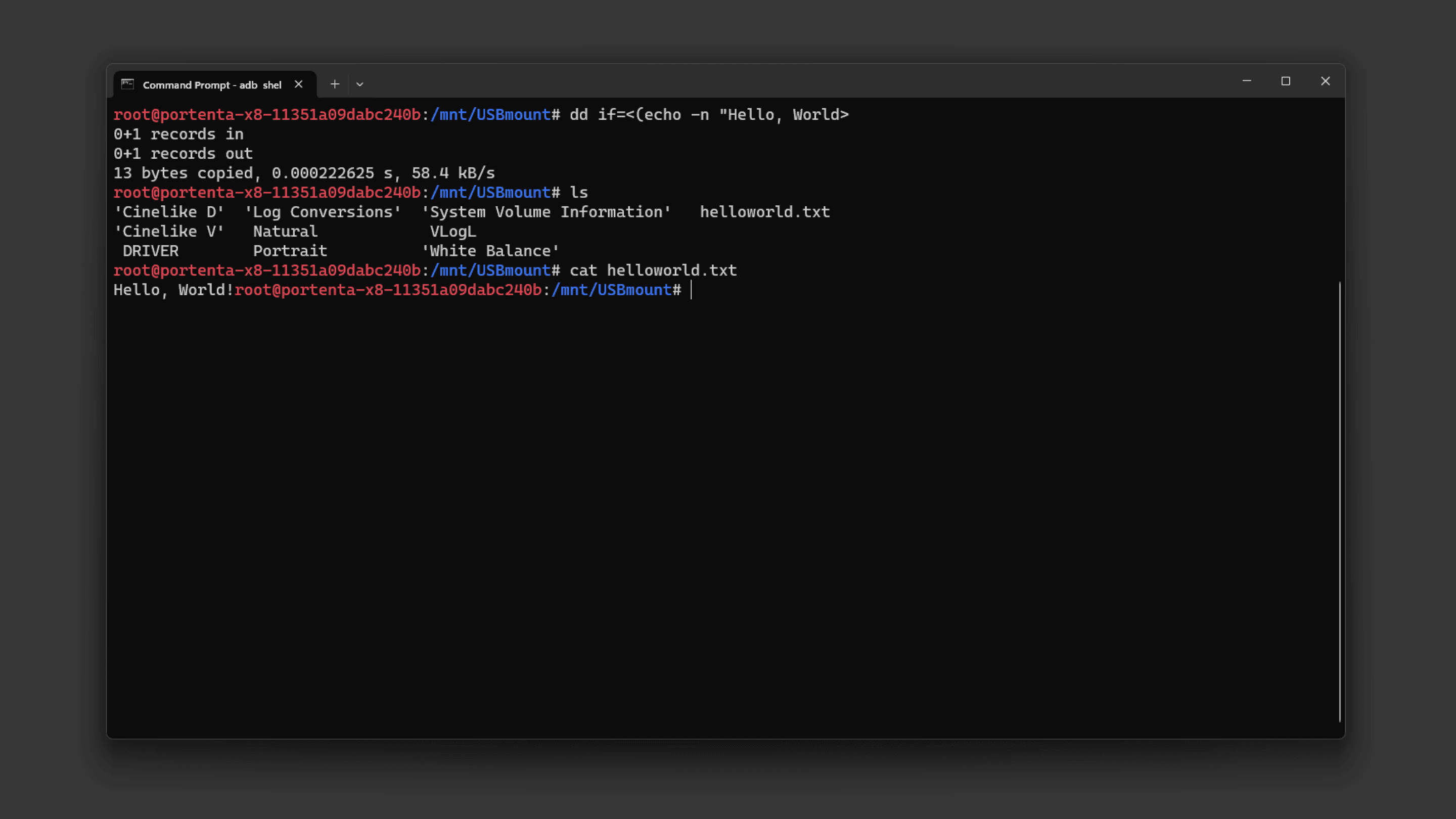
To unmount the USB drive use the following command from outside the USB folder:
1umount /dev/sda1 /mnt/USBmountNow that you know how to locate, mount, write and read information from an external USB stick or hard drive, you can expand the possibilities of your solution with the additional storage connected to the Portenta Max Carrier.
Using Arduino IDE
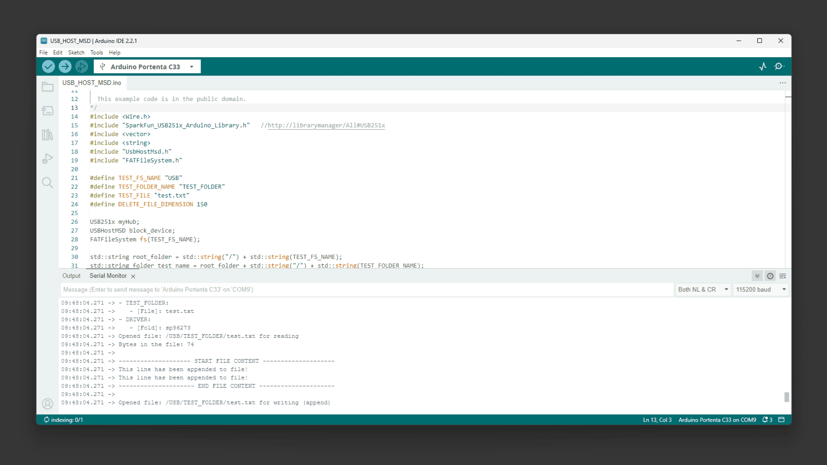
The following example demonstrates how to use the USB interface of the Portenta Max Carrier with the Portenta C33 to mount a Mass Storage Device (MSD).
The Max Carrier uses a USB hub IC (USB2514B) that manages the communication between the two USB-A ports and the USB interface of the Portenta SoM. To use it with the Arduino IDE, a library is needed and you can install it by searching for
USB251XThrough this code, users will be able to effectively connect to, read from, and write to a USB storage device, making it easier to interact with external storage via the USB interface.
1#include <Wire.h>2#include "SparkFun_USB251x_Arduino_Library.h" //Click here to install: http://librarymanager/All#USB251x3#include <vector>4#include <string>5#include "UsbHostMsd.h"6#include "FATFileSystem.h"7
8#define TEST_FS_NAME "USB"9#define TEST_FOLDER_NAME "TEST_FOLDER"10#define TEST_FILE "test.txt"11#define DELETE_FILE_DIMENSION 15012
13USB251x myHub;14USBHostMSD block_device;15FATFileSystem fs(TEST_FS_NAME);16
17std::string root_folder = std::string("/") + std::string(TEST_FS_NAME);18std::string folder_test_name = root_folder + std::string("/") + std::string(TEST_FOLDER_NAME);19std::string file_test_name = folder_test_name + std::string("/") + std::string(TEST_FILE);20
21/* this callback will be called when a Mass Storage Device is plugged in */22void device_attached_callback(void) {23 Serial.println();24 Serial.println("++++ Mass Storage Device detected ++++");25 Serial.println();26}27
28void setup() {29 /*30 * SERIAL INITIALIZATION31 */32 Serial.begin(115200);33 while (!Serial) {34 }35
36 Wire.begin();37
38 if (myHub.begin() == false) {39 Serial.println("Device not found. USB251xB may already be in hub mode. Please check wiring or reset the hub. Freezing...");40 while (1)41 ;42 }43
44 Serial.println("Writing default settings to hub");45 myHub.setDefaults(); //Write ROM defaults46 myHub.attach(); //Locks settings and begin acting as hub47
48
49 Serial.println();50 Serial.println("*** USB HOST Mass Storage Device example ***");51 Serial.println();52
53 /* attach the callback so that when the device is inserted the device_attached_callback54 will be automatically called */55 block_device.attach_detected_callback(device_attached_callback);56 /* list to store all directory in the root */57 std::vector<std::string> dir_list;58
59 /* 60 * Check for device to be connected61 */62
63 int count = 0;64 while (!block_device.connect()) {65 if (count == 0) {66 Serial.println("Waiting for Mass Storage Device");67 } else {68 Serial.print(".");69 if (count % 30 == 0) {70 Serial.println();71 }72 }73 count++;74 delay(1000);75 }76
77 Serial.println("Mass Storage Device connected.");78
79 /* 80 * MOUNTIN SDCARD AS FATFS filesystem81 */82
83 Serial.println("Mounting Mass Storage Device...");84 int err = fs.mount(&block_device);85 if (err) {86 // Reformat if we can't mount the filesystem87 // this should only happen on the first boot88 Serial.println("No filesystem found, formatting... ");89 err = fs.reformat(&block_device);90 }91
92 if (err) {93 Serial.println("Error formatting USB Mass Storage Device");94 while (1)95 ;96 }97
98 /* 99 * READING root folder100 */101
102 DIR *dir;103 struct dirent *ent;104 int dirIndex = 0;105
106 Serial.println("*** List USB Mass Storage Device content: ");107 if ((dir = opendir(root_folder.c_str())) != NULL) {108 while ((ent = readdir(dir)) != NULL) {109 if (ent->d_type == DT_REG) {110 Serial.print("- [File]: ");111 } else if (ent->d_type == DT_DIR) {112 Serial.print("- [Fold]: ");113 if (ent->d_name[0] != '.') { /* avoid hidden folders (.Trash might contain a lot of files) */114 dir_list.push_back(ent->d_name);115 }116 }117 Serial.println(ent->d_name);118 dirIndex++;119 }120 closedir(dir);121 } else {122 // Could not open directory123 Serial.println("Error opening USB Mass Storage Device\n");124 while (1)125 ;126 }127
128 if (dirIndex == 0) {129 Serial.println("Empty SDCARD");130 }131
132 bool found_test_folder = false;133
134 /* 135 * LISTING CONTENT of the first level folders (the one immediately present in root folder)136 */137
138 if (dir_list.size()) {139 Serial.println();140 Serial.println("Listing content of folders in root: ");141 }142 for (unsigned int i = 0; i < dir_list.size(); i++) {143 if (dir_list[i] == TEST_FOLDER_NAME) {144 found_test_folder = true;145 }146 Serial.print("- ");147 Serial.print(dir_list[i].c_str());148 Serial.println(":");149
150 std::string d = root_folder + std::string("/") + dir_list[i];151 if ((dir = opendir(d.c_str())) != NULL) {152 while ((ent = readdir(dir)) != NULL) {153 if (ent->d_type == DT_REG) {154 Serial.print(" - [File]: ");155 } else if (ent->d_type == DT_DIR) {156 Serial.print(" - [Fold]: ");157 }158 Serial.println(ent->d_name);159 }160 closedir(dir);161 } else {162 Serial.print("ERROR OPENING SUB-FOLDER ");163 Serial.println(d.c_str());164 }165 }166
167 /* 168 * CREATING TEST FOLDER (if does not exist already)169 */170
171 err = 0;172 if (!found_test_folder) {173 Serial.println("TEST FOLDER NOT FOUND... creating folder test");174 err = mkdir(folder_test_name.c_str(), S_IRWXU | S_IRWXG | S_IRWXO);175 if (err != 0) {176 Serial.print("FAILED folder creation with error ");177 Serial.println(err);178 }179 }180
181 /* 182 * READING TEST FILE CONTENT183 */184
185 if (err == 0) {186 int file_dimension = 0;187 FILE *fp = fopen(file_test_name.c_str(), "r");188 if (fp != NULL) {189 Serial.print("Opened file: ");190 Serial.print(file_test_name.c_str());191 Serial.println(" for reading");192
193 fseek(fp, 0L, SEEK_END);194 int numbytes = ftell(fp);195 fseek(fp, 0L, SEEK_SET);196
197 Serial.print("Bytes in the file: ");198 Serial.println(numbytes);199 file_dimension = numbytes;200
201 if (numbytes > 0) {202 Serial.println();203 Serial.println("-------------------- START FILE CONTENT --------------------");204 }205
206 for (int i = 0; i < numbytes; i++) {207 char ch;208 fread(&ch, sizeof(char), 1, fp);209 Serial.print(ch);210 }211
212 if (numbytes > 0) {213 Serial.println("--------------------- END FILE CONTENT ---------------------");214 Serial.println();215 } else {216 Serial.println("File is EMPTY!");217 Serial.println();218 }219
220 fclose(fp);221 } else {222 Serial.print("FAILED open file ");223 Serial.println(file_test_name.c_str());224 }225
226 /*227 * DELETE FILE IF THE File dimension is greater than 150 bytes228 */229
230 if (file_dimension > DELETE_FILE_DIMENSION) {231 Serial.println("Test file reached the delete dimension... deleting it!");232 if (remove(file_test_name.c_str()) == 0) {233 Serial.println("TEST FILE HAS BEEN DELETED!");234 }235 }236
237 /*238 * APPENDING SOMETHING TO FILE 239 */240
241 fp = fopen(file_test_name.c_str(), "a");242 if (fp != NULL) {243 Serial.print("Opened file: ");244 Serial.print(file_test_name.c_str());245 Serial.println(" for writing (append)");246 char text[] = "This line has been appended to file!\n";247 fwrite(text, sizeof(char), strlen(text), fp);248 fclose(fp);249 } else {250 Serial.print("FAILED open file for appending ");251 Serial.println(file_test_name.c_str());252 }253
254 /*255 * READING AGAIN FILE CONTENT256 */257
258 fp = fopen(file_test_name.c_str(), "r");259 if (fp != NULL) {260 Serial.print("Opened file: ");261 Serial.print(file_test_name.c_str());262 Serial.println(" for reading");263
264 fseek(fp, 0L, SEEK_END);265 int numbytes = ftell(fp);266 fseek(fp, 0L, SEEK_SET);267
268 Serial.print("Bytes in the file: ");269 Serial.println(numbytes);270
271 if (numbytes > 0) {272 Serial.println();273 Serial.println("-------------------- START FILE CONTENT --------------------");274 }275
276 for (int i = 0; i < numbytes; i++) {277 char ch;278 fread(&ch, sizeof(char), 1, fp);279 Serial.print(ch);280 }281
282 if (numbytes > 0) {283 Serial.println("--------------------- END FILE CONTENT ---------------------");284 Serial.println();285 } else {286 Serial.println("File is EMPTY!");287 Serial.println();288 }289
290 fclose(fp);291
292 } else {293 Serial.print("FAILED open file for appending ");294 Serial.println(file_test_name.c_str());295 }296 }297}298
299void loop() {300 // Empty301}The example code from above will read the USB drive connected and print all its content on the Serial Monitor. Also, it will create a test file.
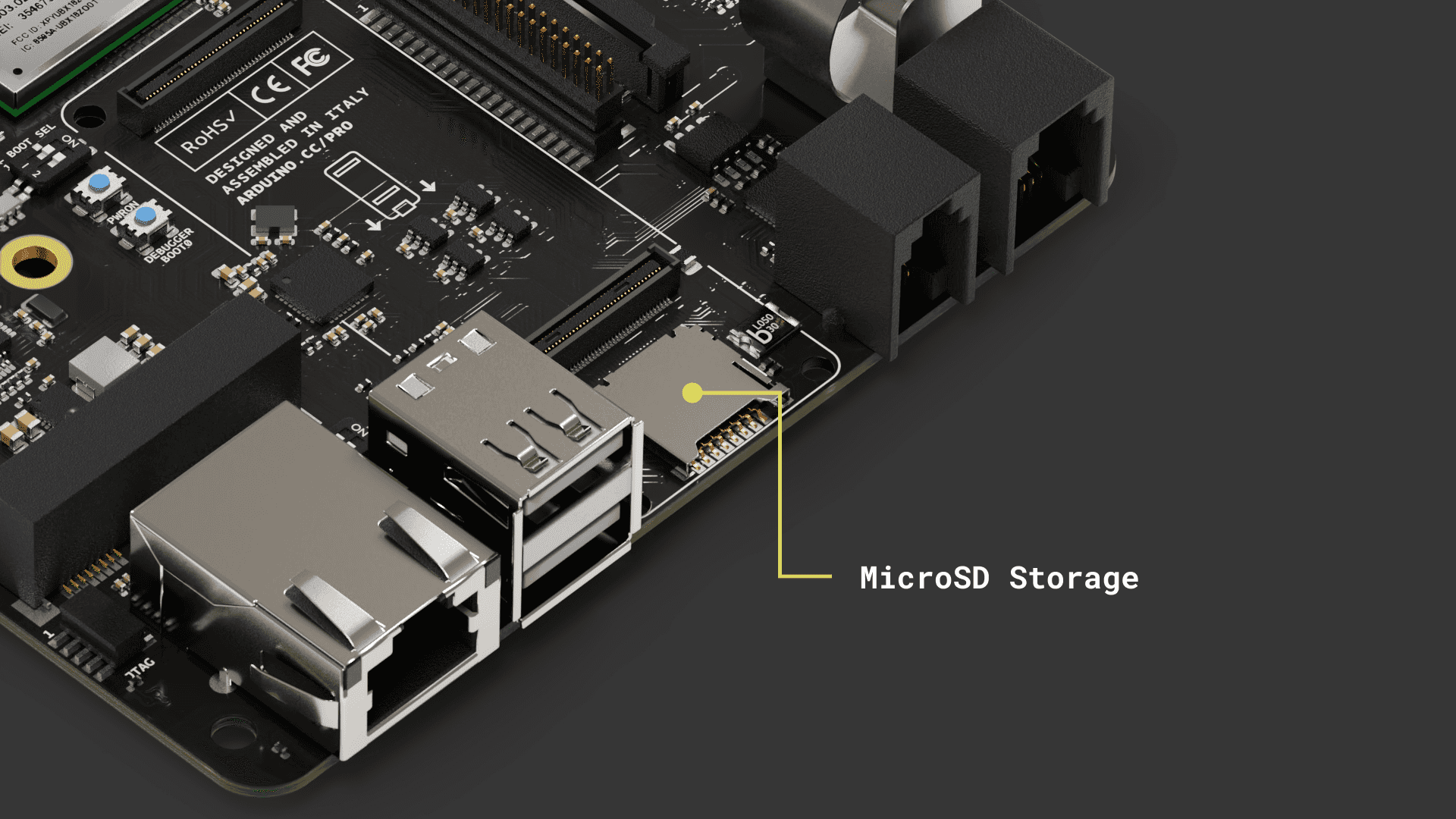
MicroSD Storage
The available microSD card slot offers the advantage of expanded storage. This is especially beneficial for processing large volumes of log data, whether from sensors or the onboard computer registry.
Using Linux
To begin using a microSD card, enter to your Portenta X8 using
adb shellsudo su -fioUse the following command to pull a Docker container that assists in setting up the necessary elements for interacting with the microSD card:
1docker run -it --cap-add SYS_ADMIN --device /dev/mmcblk1p1 debian:stable-slim bashThe command above will run the image immediately after the container image has been successfully pulled. You will find yourself inside the container once it is ready for use.
You will need to identify the partition scheme where the microSD card is located. If a partition table does not exist for the microSD card, you will have to use the
fdiskInside the container, you can use the following commands.
To determine if the Portenta X8 has recognized the microSD card, you can use one of the following commands:
1lsblk2
3# or4fdisk -lThe microSD card usually appears as
/dev/mmcblk0/dev/sdXBefore accessing the contents of the microSD card, it needs to be mounted. For convenient operation, create a directory that will serve as the mount point:
1mkdir -p /tmp/sdcardUse the following command to mount the microSD card to the previously created directory. Ensure you replace
XX1mount /dev/mmcblk1p1 /tmp/sdcardNavigate to the mount point and list the contents of the SD card:
1cd /tmp/sdcard2ls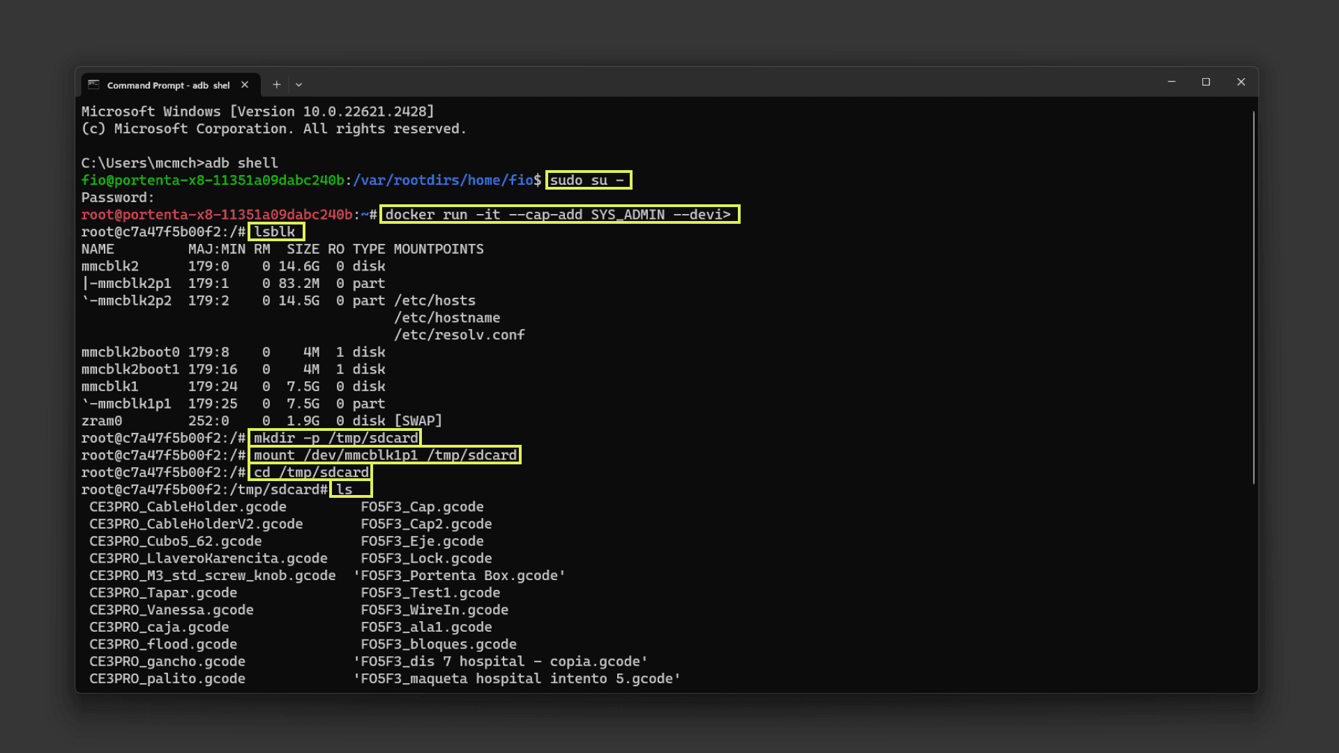
To write data to the microSD card, you can use the
echohello.txt"Hello World Carrier!"1echo "Hello World Carrier!" > hello.txtTo read the contents of the file you have just created:
1cat hello.txtThis will print on your shell the contents that were saved to the
hello.txtOnce you are done with the operations related to microSD card, it is important to unmount it properly:
1umount /tmp/sdcard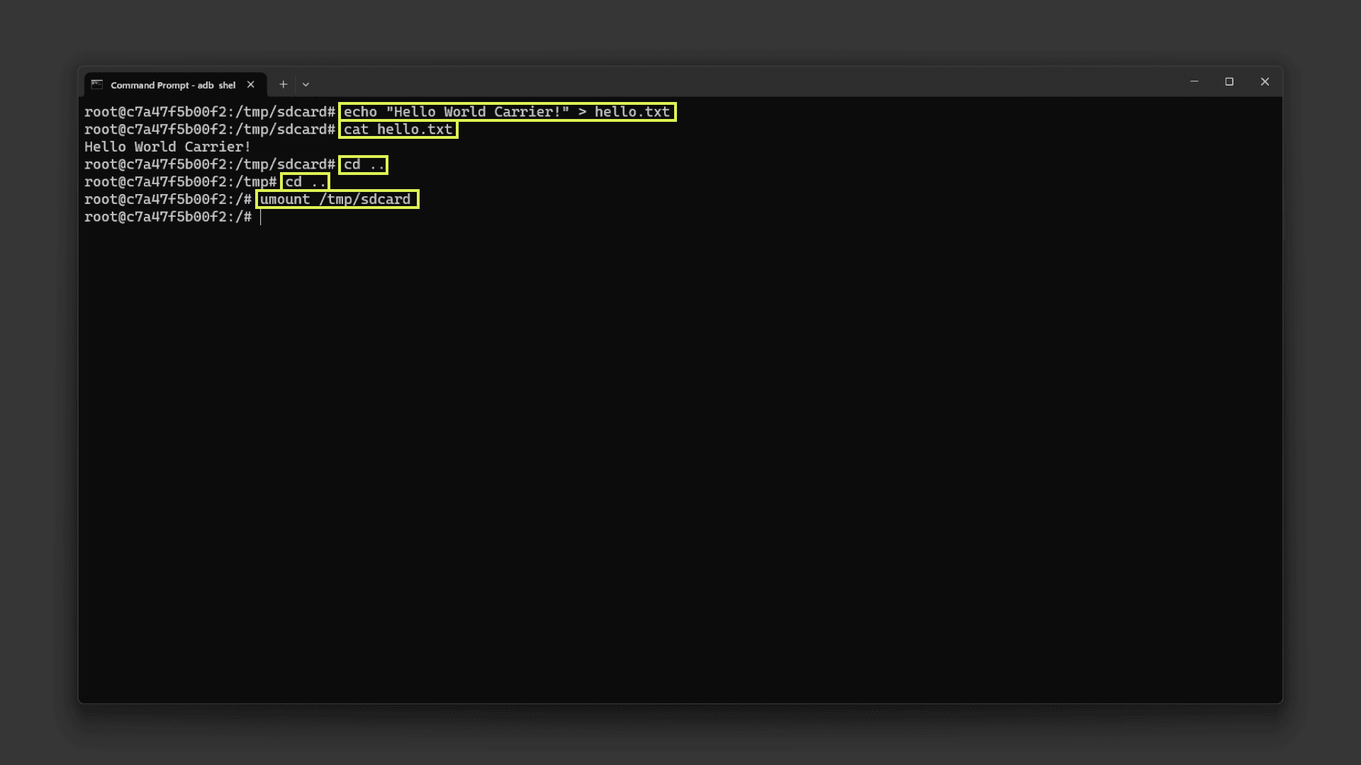
Warning: If you need to format the micro SD card to the ext4 filesystem, use the following command.
Please be cautious, since this command will erase all the existing data on the microSD card.
1mkfs.ext4 /dev/mmcblk1p1 #Warning: this will erase everything on your micro SDUsing Arduino IDE
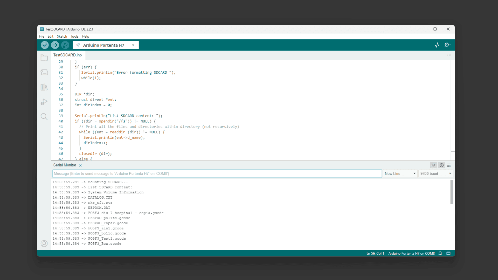
For Portenta H7, you can use the following Arduino IDE script to test the mounted SD card within Portenta Max Carrier:
This example can also be found on the Arduino IDE built-in examples on File > Examples > Portenta_SDCARD > TestSDCARD
1#include "SDMMCBlockDevice.h"2#include "FATFileSystem.h"3
4SDMMCBlockDevice block_device;5mbed::FATFileSystem fs("fs");6
7void setup() {8 Serial.begin(9600);9 while (!Serial);10
11 Serial.println("Mounting SDCARD...");12 int err = fs.mount(&block_device);13 if (err) {14 // Reformat if we can't mount the filesystem15 // this should only happen on the first boot16 Serial.println("No filesystem found, formatting... ");17 err = fs.reformat(&block_device);18 }19 if (err) {20 Serial.println("Error formatting SDCARD ");21 while(1);22 }23 24 DIR *dir;25 struct dirent *ent;26 int dirIndex = 0;27
28 Serial.println("List SDCARD content: ");29 if ((dir = opendir("/fs")) != NULL) {30 // Print all the files and directories within directory (not recursively)31 while ((ent = readdir (dir)) != NULL) {32 Serial.println(ent->d_name);33 dirIndex++;34 }35 closedir (dir);36 } else {37 // Could not open directory38 Serial.println("Error opening SDCARD\n");39 while(1);40 }41 if(dirIndex == 0) {42 Serial.println("Empty SDCARD");43 }44}45
46void loop() {47 // Empty48}With this code, the Portenta H7 will scan all the files and directories names on the micro SD card and list them on the Arduino IDE Serial Monitor.
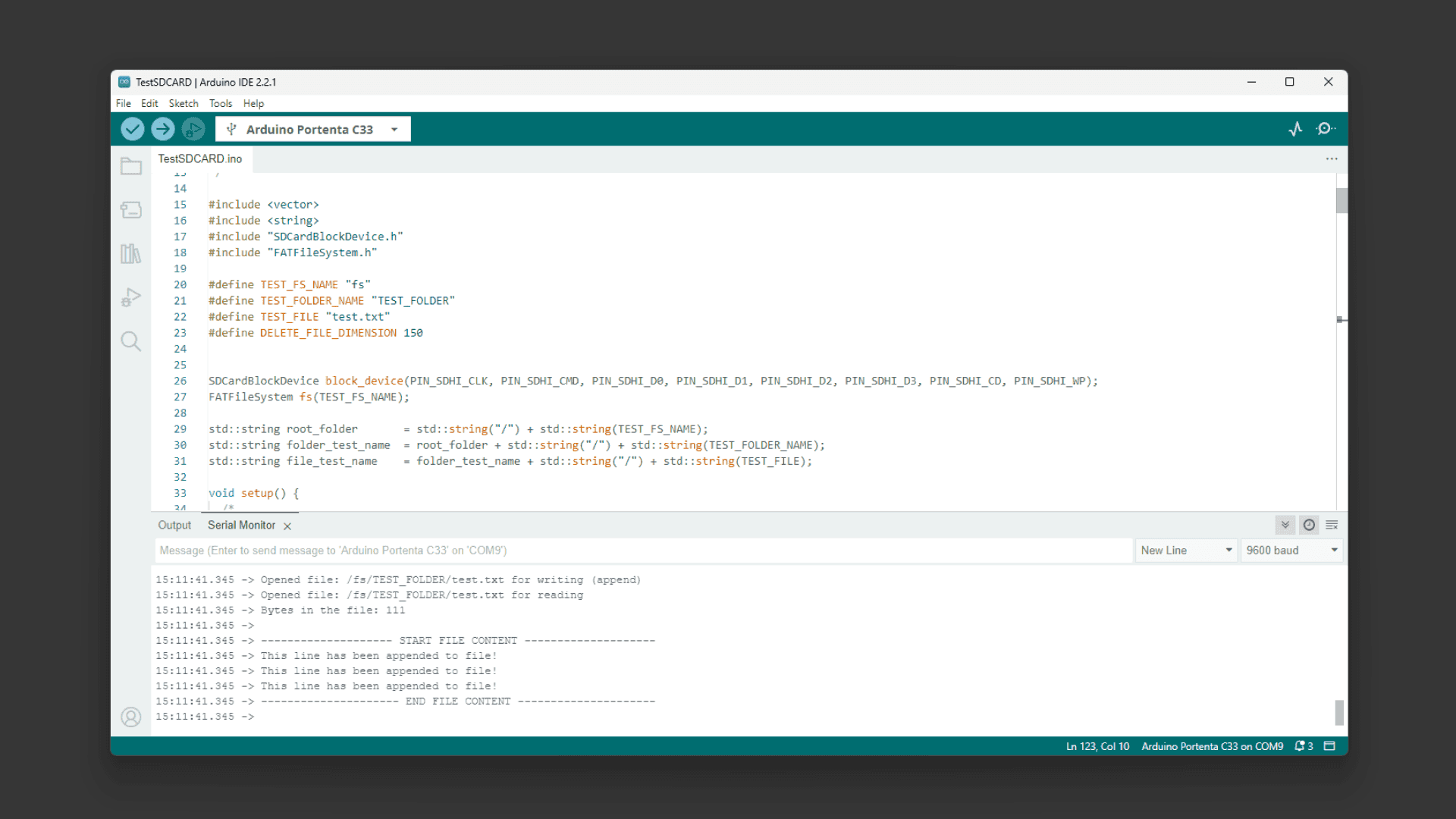
For Portenta C33, you can use the following Arduino IDE script:
This example can also be found on the Arduino IDE built-in examples on File > Examples > Storage > TestSDCARD.
1#include <vector>2#include <string>3#include "SDCardBlockDevice.h"4#include "FATFileSystem.h"5
6#define TEST_FS_NAME "fs"7#define TEST_FOLDER_NAME "TEST_FOLDER"8#define TEST_FILE "test.txt"9#define DELETE_FILE_DIMENSION 15010
11
12SDCardBlockDevice block_device(PIN_SDHI_CLK, PIN_SDHI_CMD, PIN_SDHI_D0, PIN_SDHI_D1, PIN_SDHI_D2, PIN_SDHI_D3, PIN_SDHI_CD, PIN_SDHI_WP);13FATFileSystem fs(TEST_FS_NAME);14
15std::string root_folder = std::string("/") + std::string(TEST_FS_NAME);16std::string folder_test_name = root_folder + std::string("/") + std::string(TEST_FOLDER_NAME);17std::string file_test_name = folder_test_name + std::string("/") + std::string(TEST_FILE); 18
19void setup() {20 /*21 * SERIAL INITIALIZATION22 */23 Serial.begin(9600);24 while(!Serial) {25 26 }27
28 /* list to store all directory in the root */29 std::vector<std::string> dir_list;30
31 Serial.println();32 Serial.println("##### TEST SD CARD with FAT FS");33 Serial.println();34
35 /* 36 * MOUNTING SDCARD AS FATFS filesystem37 */38 Serial.println("Mounting SDCARD...");39 int err = fs.mount(&block_device);40 if (err) {41 // Reformat if we can't mount the filesystem42 // this should only happen on the first boot43 Serial.println("No filesystem found, formatting... ");44 err = fs.reformat(&block_device);45 }46 if (err) {47 Serial.println("Error formatting SDCARD ");48 while(1);49 }50
51 /* 52 * READING root folder53 */54 55 DIR *dir;56 struct dirent *ent;57 int dirIndex = 0;58
59 Serial.println("*** List SD CARD content: ");60 if ((dir = opendir(root_folder.c_str())) != NULL) {61 while ((ent = readdir (dir)) != NULL) {62 63 if(ent->d_type == DT_REG) {64 Serial.print("- [File]: ");65 }66 67 else if(ent->d_type == DT_DIR) {68 Serial.print("- [Fold]: ");69 dir_list.push_back(ent->d_name);70 }71 Serial.println(ent->d_name);72 dirIndex++;73 }74 closedir (dir);75 } 76 else {77 // Could not open directory78 Serial.println("Error opening SDCARD\n");79 while(1);80 }81
82 if(dirIndex == 0) {83 Serial.println("Empty SDCARD");84 }85
86 bool found_test_folder = false;87
88 /* 89 * LISTING CONTENT of the first level folders (the one immediately present in root folder)90 */91
92 if(dir_list.size()) {93 Serial.println();94 Serial.println("Listing content of folders in root: ");95 }96 for(unsigned int i = 0; i < dir_list.size(); i++) {97 if(dir_list[i] == TEST_FOLDER_NAME) {98 found_test_folder = true;99 }100 Serial.print("- ");101 Serial.print(dir_list[i].c_str());102 Serial.println(":");103 104 std::string d = root_folder + std::string("/") + dir_list[i];105 if ((dir = opendir(d.c_str())) != NULL) {106 while ((ent = readdir (dir)) != NULL) {107 if(ent->d_type == DT_REG) {108 Serial.print(" - [File]: ");109 }110 else if(ent->d_type == DT_DIR) {111 Serial.print(" - [Fold]: ");112 }113 Serial.println(ent->d_name);114 }115 closedir (dir);116 }117 else {118 Serial.print("ERROR OPENING SUB-FOLDER ");119 Serial.println(d.c_str());120 }121 }122
123 /* 124 * CREATING TEST FOLDER (if does not exist already)125 */126
127 err = 0;128 if(!found_test_folder) {129 Serial.println("TEST FOLDER NOT FOUND... creating folder test"); 130 err = mkdir(folder_test_name.c_str(), S_IRWXU | S_IRWXG | S_IRWXO);131 if(err != 0) {132 Serial.print("FAILED folder creation with error ");133 Serial.println(err);134 }135 }136
137 /* 138 * READING TEST FILE CONTENT139 */140 141 if(err == 0) {142 int file_dimension = 0; 143 FILE* fp = fopen(file_test_name.c_str(), "r");144 if(fp != NULL) {145 Serial.print("Opened file: ");146 Serial.print(file_test_name.c_str());147 Serial.println(" for reading");148 149 fseek(fp, 0L, SEEK_END);150 int numbytes = ftell(fp);151 fseek(fp, 0L, SEEK_SET); 152
153 Serial.print("Bytes in the file: ");154 Serial.println(numbytes);155 file_dimension = numbytes;156
157 if(numbytes > 0) {158 Serial.println();159 Serial.println("-------------------- START FILE CONTENT --------------------");160 }161 162 for(int i = 0; i < numbytes; i++) {163 char ch;164 fread(&ch, sizeof(char), 1, fp);165 Serial.print(ch);166 }167
168 if(numbytes > 0) {169 Serial.println("--------------------- END FILE CONTENT ---------------------");170 Serial.println();171 }172 else {173 Serial.println("File is EMPTY!");174 Serial.println();175 }176 177 fclose(fp);178 }179 else {180 Serial.print("FAILED open file ");181 Serial.println(file_test_name.c_str());182 }183
184 /*185 * DELETE FILE IF THE File dimension is greater than 150 bytes186 */187
188 if(file_dimension > DELETE_FILE_DIMENSION) {189 Serial.println("Test file reached the delete dimension... deleting it!");190 if(remove(file_test_name.c_str()) == 0) {191 Serial.println("TEST FILE HAS BEEN DELETED!");192 }193 }194 195 /*196 * APPENDING SOMETHING TO FILE 197 */198 199 fp = fopen(file_test_name.c_str(), "a");200 if(fp != NULL) {201 Serial.print("Opened file: ");202 Serial.print(file_test_name.c_str());203 Serial.println(" for writing (append)");204 char text[] = "This line has been appended to file!\n";205 fwrite(text, sizeof(char), strlen(text), fp);206 fclose(fp); 207 }208 else {209 Serial.print("FAILED open file for appending ");210 Serial.println(file_test_name.c_str());211 }212 213 /*214 * READING AGAIN FILE CONTENT215 */216 217 fp = fopen(file_test_name.c_str(), "r");218 if(fp != NULL) {219 Serial.print("Opened file: ");220 Serial.print(file_test_name.c_str());221 Serial.println(" for reading");222 223 fseek(fp, 0L, SEEK_END);224 int numbytes = ftell(fp);225 fseek(fp, 0L, SEEK_SET); 226
227 Serial.print("Bytes in the file: ");228 Serial.println(numbytes);229
230 if(numbytes > 0) {231 Serial.println();232 Serial.println("-------------------- START FILE CONTENT --------------------");233 }234 235 for(int i = 0; i < numbytes; i++) {236 char ch;237 fread(&ch, sizeof(char), 1, fp);238 Serial.print(ch);239 }240
241 if(numbytes > 0) {242 Serial.println("--------------------- END FILE CONTENT ---------------------");243 Serial.println();244 }245 else {246 Serial.println("File is EMPTY!");247 Serial.println();248 }249 250 fclose(fp);251 252 }253 else {254 Serial.print("FAILED open file for appending ");255 Serial.println(file_test_name.c_str());256 }257 } 258 259}260
261void loop() {262 // Empty263}With this code, the Portenta C33 will scan all the files and directories names on the micro SD card and list them on the Arduino IDE Serial Monitor, also create a test file and read it back.
JTAG Pins
For developers aiming to investigate and understand the intricate details of development, the Portenta Max Carrier features a built-in JTAG interface. This tool is crucial for hardware debugging, offering real-time observation. Through the JTAG pins, users can smoothly debug and program, guaranteeing accurate and optimal device performance.
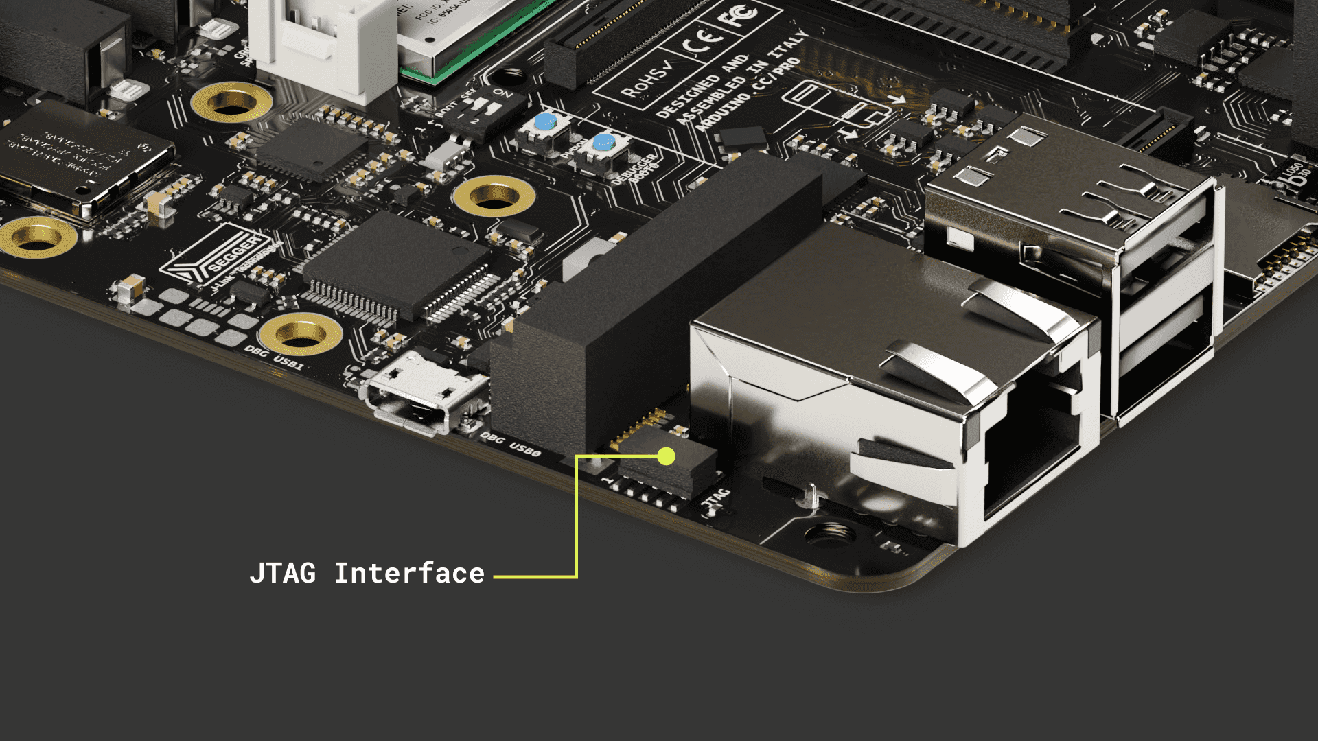
The pins used for the JTAG debug port on the Portenta Max Carrier are the following:
| Pin number | Power Net | Portenta HD Standard Pin | High-Density Pin | Interface |
|---|---|---|---|---|
| 1 | +3V3_PORTENTA | VCC | J2-23, J2-34, J2-43, J2-69 | |
| 2 | JTAG_SWD | J1-75 | JTAG SWD | |
| 3 | GND | GND | J1-22, J1-31, J1-42, J1-47, J1-54, J2-24, J2-33, J2-44, J2-57, J2-70 | |
| 4 | JTAG_SCK | J1-77 | JTAG SCK | |
| 5 | GND | GND | J1-22, J1-31, J1-42, J1-47, J1-54, J2-24, J2-33, J2-44, J2-57, J2-70 | |
| 6 | JTAG_SWO | J1-79 | JTAG SWO | |
| 7 | NC | NC | ||
| 8 | JTAG_TDI | J1-78 | JTAG TDI | |
| 9 | JTAG_TRST | J1-80 | JTAG TRST | |
| 10 | JTAG_RST | J1-73 | JTAG RST |
Communication
CAN Bus
The CAN bus, short for Controller Area Network bus, is a resilient communication protocol created by Bosch® in the 1980s for vehicles. It lets microcontrollers and devices interact without a central computer. Using a multi-master model, any system device can send data when the bus is available.
This approach ensures system continuity even if one device fails and is especially effective in electrically noisy settings like in vehicles, where various devices need reliable communication.
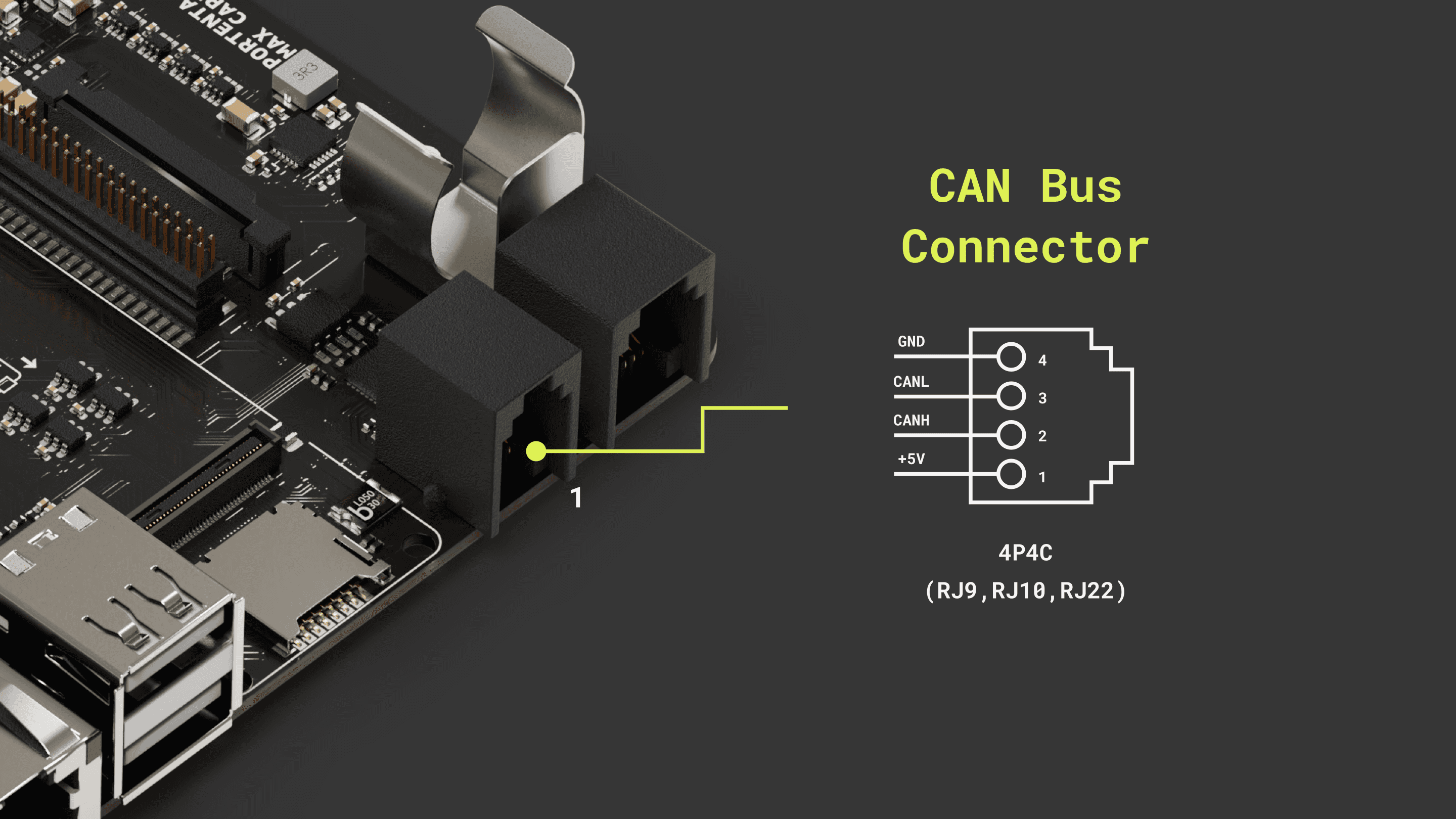
The Portenta Max Carrier is equipped with CAN bus communication capabilities, powered by the TJA1049 module - a high-speed CAN FD transceiver. With this, developers can leverage the robustness and efficiency of CAN communication in their projects.
Using Linux
As a practical example, we are going to implement a communication between the Max Carrier using a Portenta X8 and a Portenta Machine Control using CAN.
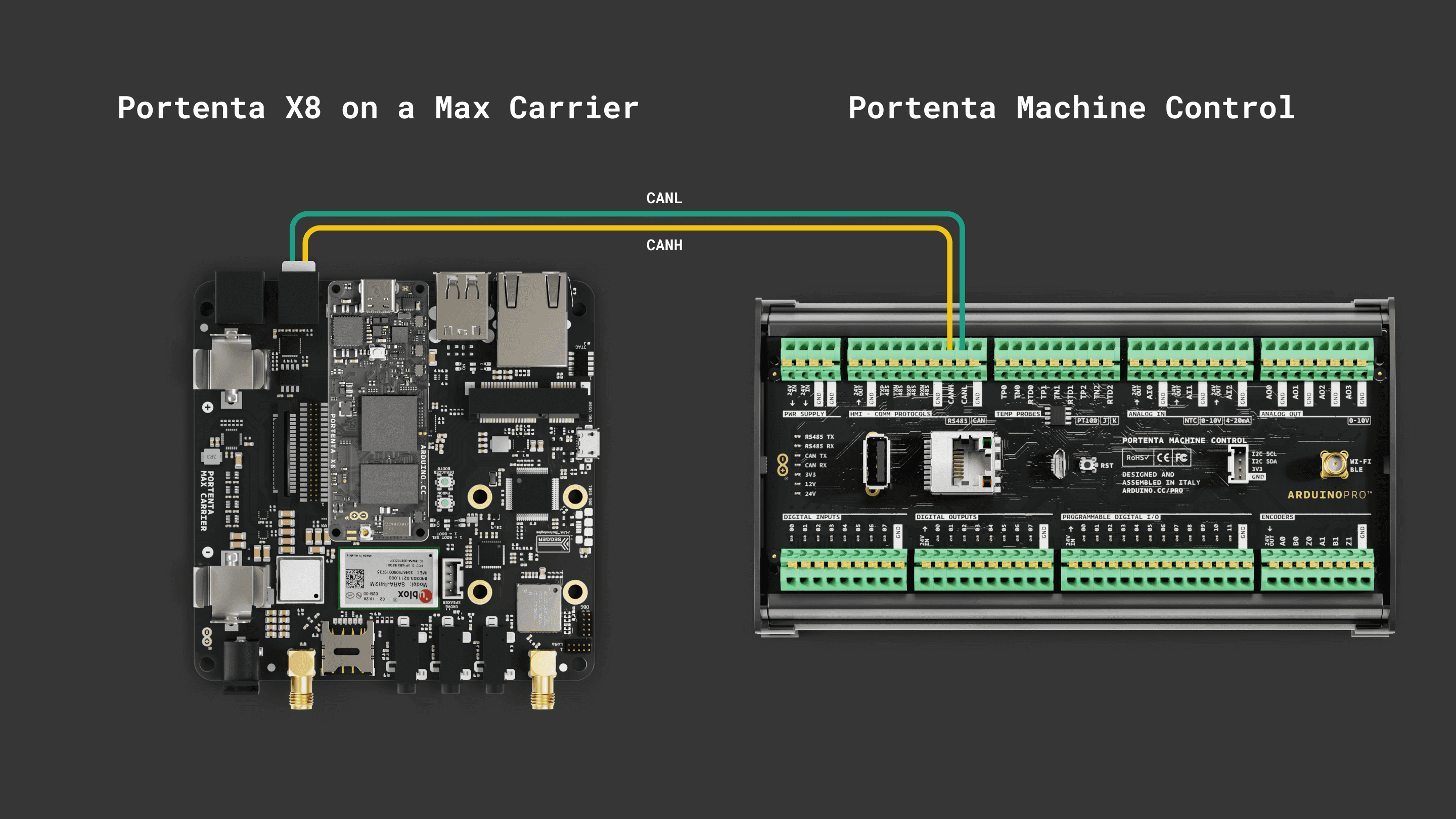
For stable CAN bus communication, it is recommended to install 120 Ω termination resistors between CANH and CANL lines.
For the Portenta X8, when you have admin (root) access, you can execute the following lines of code within the shell to control the CAN bus interface. The CAN transceiver can be enabled using the following command:
echo 186 > /sys/class/gpio/export && echo out > /sys/class/gpio/gpio186/direction && echo 0 > /sys/class/gpio/gpio186/valueThis command sequence activates the CAN transceiver. It does so by exporting GPIO 186 (
pwm3out0It is possible to use the following commands:
1sudo modprobe can-devThe necessary modules for CAN (Controller Area Network) support on the Portenta X8 are loaded. The
can-dev1echo "can-dev" | sudo tee > /etc/modules-load.d/can-dev.conf2sudo systemctl rebootWithin the Portenta X8's shell, Docker containers offer a streamlined environment for specific tasks, such as command-based CAN bus operations. The
cansendTo use the
cansend1git clone https://github.com/pika-spark/pika-spark-containersNavigate to the can-utils-sh directory:
1cd pika-spark-containers/can-utils-shBuild the Docker container:
1./docker-build.shRun the Docker container with the desired bitrate:
1sudo ./docker-run.sh can0 [bitrate]As an example, the command can be structured as follows for a 500 kbit/s communication:
1sudo ./docker-run.sh can0 500000Now, you can send CAN messages using the
cansend1cansend can0 123#CAThe command follows the format:
cansend <CAN Interface [can0 | can1]> <CAN ID>#<Data_Payload>
: defines the CAN interface (can0 to use the onboard transeiver).<CAN Interface [can0 | can1]>
: is the identifier of the message and is used for message prioritization. The identifier can be in 11-bit or 29-bit format both HEX.<CAN ID>
: is the data payload of the CAN message and ranges from 0 to 8 bytes in standard CAN frames.<Data_Payload>
This is how the communication is done between the Max Carrier with the Portenta X8 and the Machine Control.
For the Portenta Machine Control: Install the
Arduino_PortentaMachineControl1#include <Arduino_PortentaMachineControl.h>2
3void setup() {4 Serial.begin(9600);5 while (!Serial) {6 ; // wait for serial port to connect.7 }8
9 if (!MachineControl_CANComm.begin(CanBitRate::BR_500k)) {10 Serial.println("CAN init failed.");11 while(1) ;12 }13}14
15void loop() {16 if (MachineControl_CANComm.available()) {17 CanMsg const msg = MachineControl_CANComm.read();18 // Print the sender ID19 Serial.print("ID: ");20 Serial.println(msg.id, HEX);21
22 // Print the first Payload Byte23 Serial.print("Message received: ");24 Serial.println(msg.data[0], HEX);25 }26}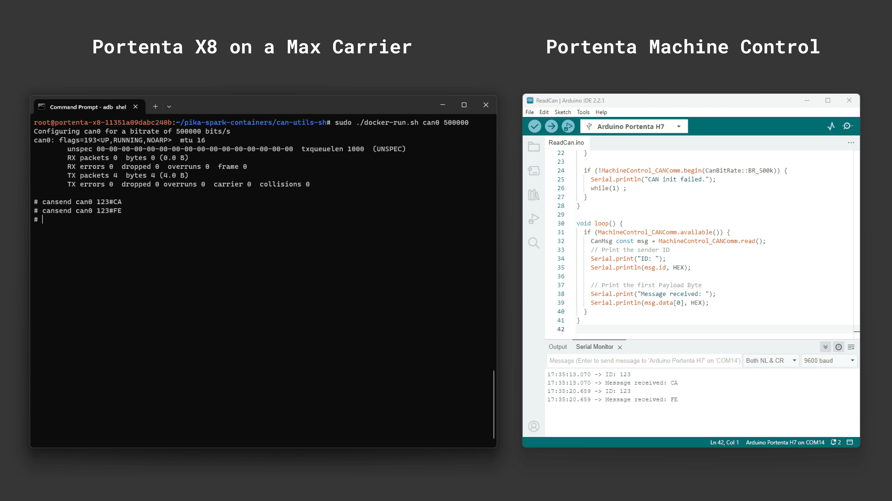
Moreover, if your goal is to monitor and dump all received CAN frames, a slightly different procedure has to be followed. When the container repository is ready with its components, navigate to the candump directory:
1cd pika-spark-containers/candumpBuild the Docker container:
1./docker-build.shNow, you are able to receive CAN messages running this command:
1sudo ./docker-run.sh can0 500000 # last parameter is the bitrateThis is how the communication is done between the Max Carrier with the Portenta X8 and the Machine Control.
For the Portenta Machine Control: Install the
Arduino_PortentaMachineControl1#include <Arduino_MachineControl.h>2#include <CAN.h>3using namespace machinecontrol;4
5#define DATARATE_500KB 5000006
7void setup() {8 Serial.begin(9600);9 while (!Serial) {10 ; // wait for serial port to connect.11 }12
13 Serial.println("Start CAN initialization");14 comm_protocols.enableCAN();15 comm_protocols.can.frequency(DATARATE_500KB);16 Serial.println("Initialization done");17}18
19int counter = 0;20unsigned char payload = 0x49;21int payload_size = 1;22
23void loop() {24
25 mbed::CANMessage msg = mbed::CANMessage(13ul, &payload, payload_size);26 if (comm_protocols.can.write(msg)) {27 Serial.println("Message sent");28 } else {29 Serial.println("Transmission Error: ");30 Serial.println(comm_protocols.can.tderror());31 comm_protocols.can.reset();32 }33
34 delay(1000);35}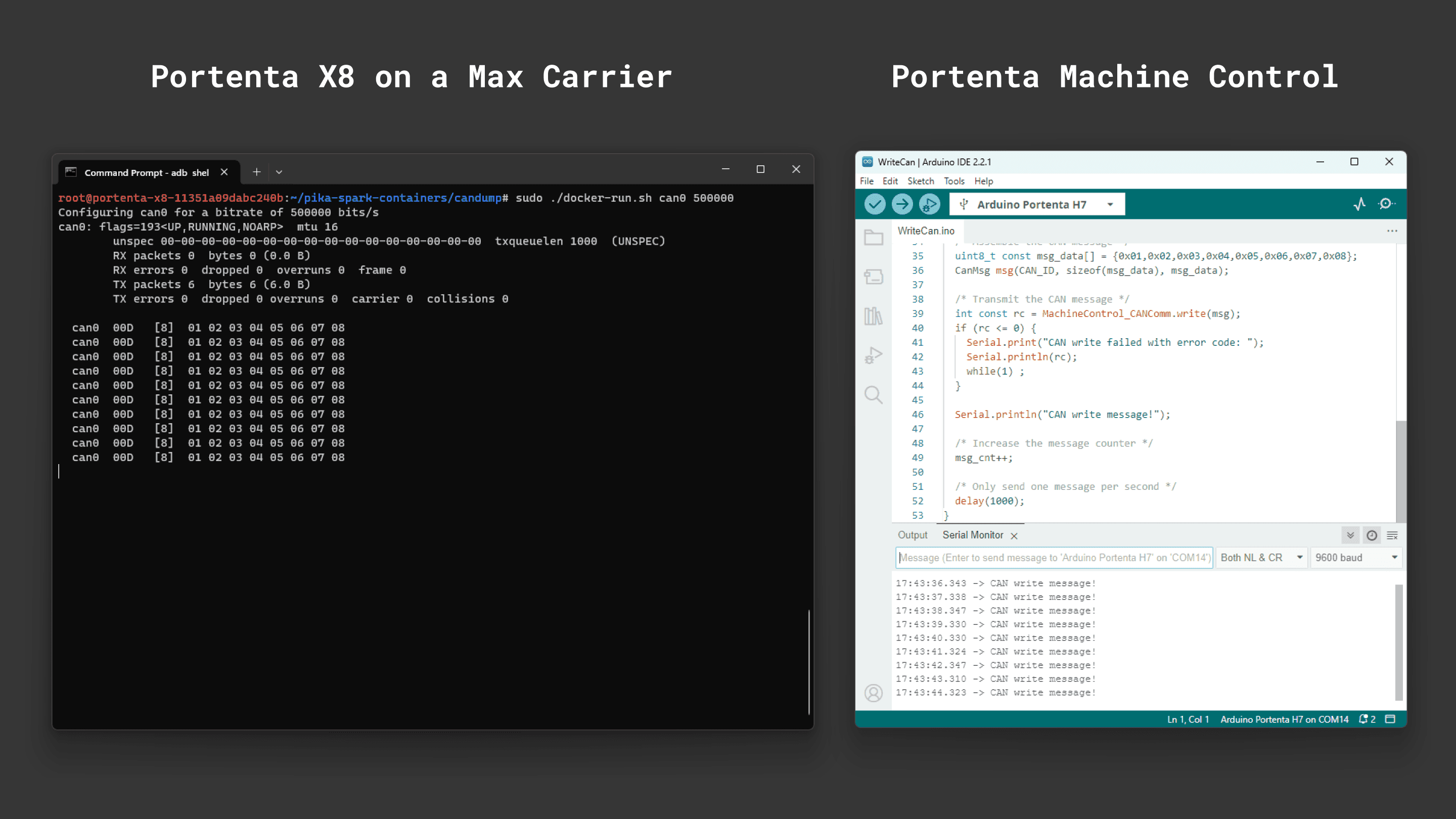
Using Arduino IDE
For users working with the Portenta C33, the following simple examples can be used to test the CAN bus protocol's capabilities.
CAN communication is not supported for the Portenta H7 on the Max Carrier.
The CAN Read example for Portenta C33 starts CAN communication at a rate of 500 kbps and continuously listens for incoming messages, displaying such information upon receipt.
1#include <Arduino_CAN.h>2
3void setup()4{5 Serial.begin(115200);6
7 while (!Serial) { } // open the serial monitor to start receiving8
9 if (!CAN.begin(CanBitRate::BR_500k))10 {11 Serial.println("CAN.begin(...) failed.");12 for (;;) {}13 }14 Serial.println("CAN.begin(...) Successful.");15}16
17void loop()18{19 if (CAN.available())20 {21 CanMsg const msg = CAN.read();22 Serial.println(msg);23 }24}The CAN Write example, also set at 500 kbps, builds and sends a specific message format. This message includes a fixed preamble followed by an incrementing counter value that updates with each loop iteration.
1#include <Arduino_CAN.h>2
3static uint32_t const CAN_ID = 0x20;4
5void setup()6{7 Serial.begin(115200);8
9 while (!Serial) { } // open the serial monitor to start sending10
11 if (!CAN.begin(CanBitRate::BR_500k))12 {13 Serial.println("CAN.begin(...) failed.");14 for (;;) {}15 }16 Serial.println("CAN.begin(...) Successful.");17}18
19static uint32_t msg_cnt = 0;20
21void loop()22{23 /* Assemble a CAN message with the format of24 * 0xCA 0xFE 0x00 0x00 [4 byte message counter]25 */26 uint8_t const msg_data[] = {0xCA,0xFE,0,0,0,0,0,0};27 memcpy((void *)(msg_data + 3), &msg_cnt, sizeof(msg_cnt));28 CanMsg const msg(CanStandardId(CAN_ID), sizeof(msg_data), msg_data);29
30 /* Transmit the CAN message, capture and display an31 * error core in case of failure.32 */33 if (int const rc = CAN.write(msg); rc < 0)34 {35 Serial.print ("CAN.write(...) failed with error code ");36 Serial.println(rc);37 for (;;) { }38 }39
40 /* Increase the message counter. */41 msg_cnt++;42
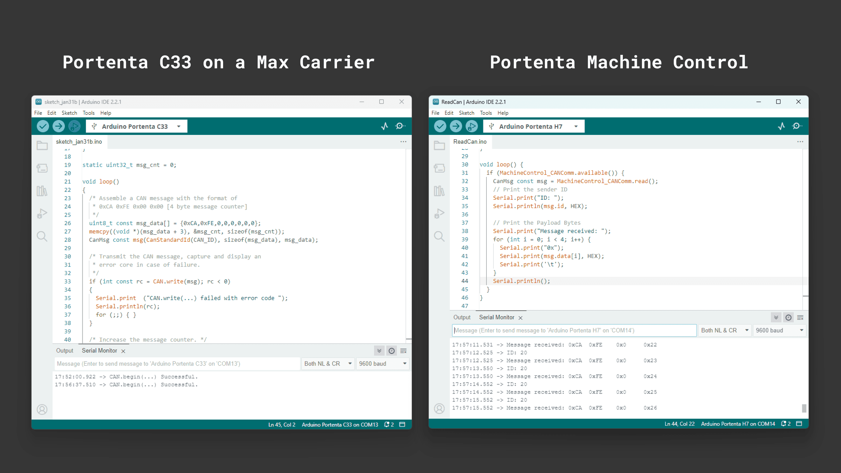
43 /* Only send one message per second. */44 delay(1000);45}As a practical example, we are going to implement the communication between the Max Carrier with a Portenta C33 and a Portenta Machine Control using CAN.
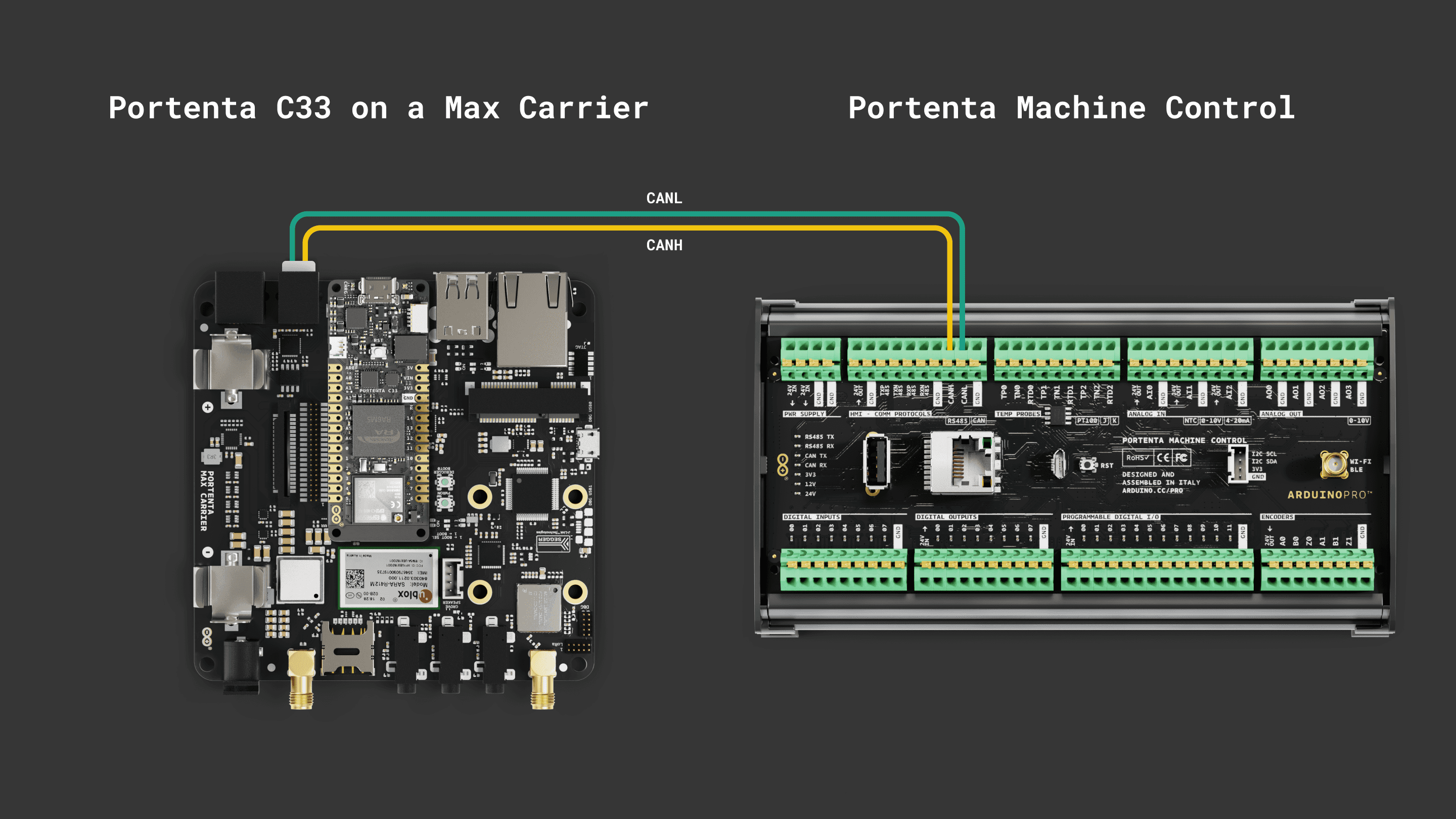
For stable CAN bus communication, it is recommended to install 120 Ω termination resistors between CANH and CANL lines.
- For the Portenta C33: Use the writing example from above.
- For the Portenta Machine Control: Install the
library from the Library Manager and use the following example sketch:Arduino_PortentaMachineControl.h
1#include <Arduino_PortentaMachineControl.h>2
3void setup() {4 Serial.begin(9600);5 while (!Serial) {6 ; // wait for serial port to connect.7 }8
9 if (!MachineControl_CANComm.begin(CanBitRate::BR_500k)) {10 Serial.println("CAN init failed.");11 while(1) ;12 }13}14
15void loop() {16 if (MachineControl_CANComm.available()) {17 CanMsg const msg = MachineControl_CANComm.read();18 // Print the sender ID19 Serial.print("ID: ");20 Serial.println(msg.id, HEX);21
22 // Print the Payload Bytes23 Serial.print("Message received: ");24 for (int i = 0; i < 4; i++) {25 Serial.print("0x");26 Serial.print(msg.data[i], HEX);27 Serial.print('\t');28 }29 Serial.println();30 }31}Remember that the Portenta Machine Control must be programmed by selecting the
Portenta H7After uploading the code to the Max Carrier and the Machine Control, open both Serial Monitors and you will see the CAN messages exchange.
Serial RS-232/RS-485
The Portenta Max Carrier includes a multi-protocol transceiver supporting RS-232, RS-485, and RS-422 serial standards (configurable) based on the SP335 IC.
Default configuration:
- Full Duplex
- 232 protocol
- No data rate limit
- Enabled
Here is the connector pinout for reference:
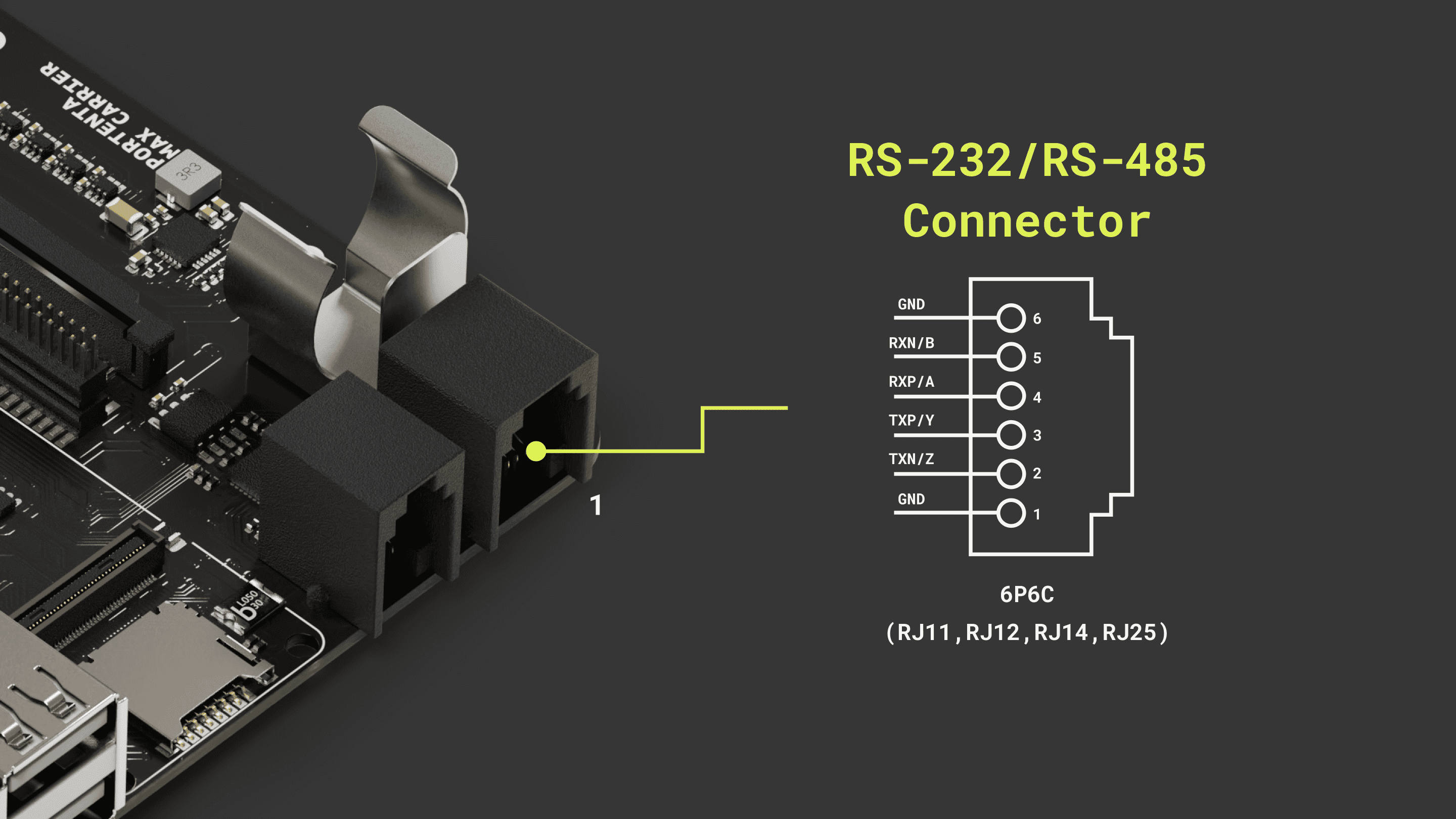
We are going to implement the communication between the Portenta Max Carrier and the Machine Control leveraging two different protocols,
RS-485RS-232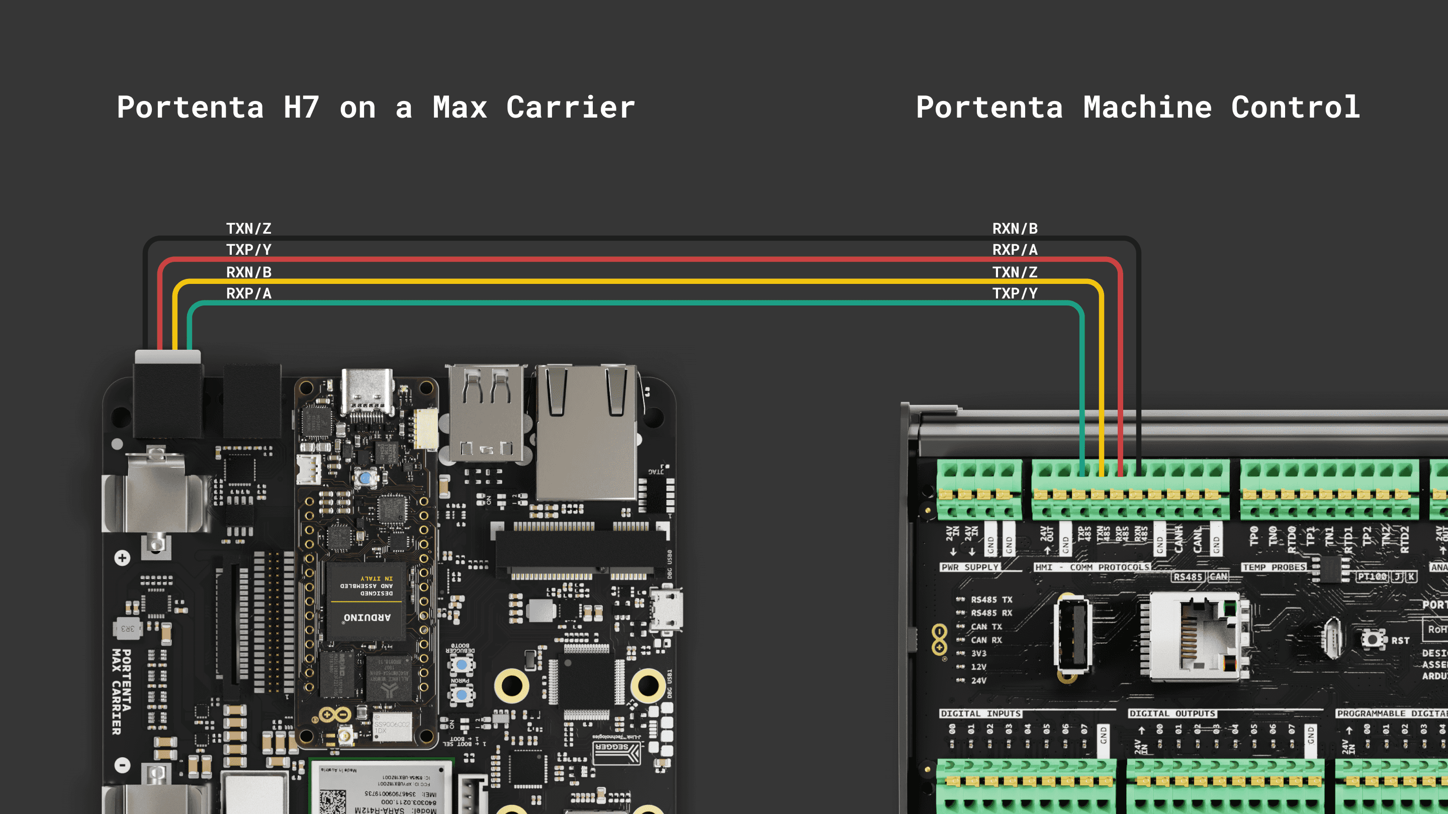
Using Linux
In the Portenta Max Carrier, the UART used for the RS-232/485 transceiver is the
UART0ttyX0To set up the serial communication so it matches the link requirements, we can configure the port baud rate, parity and stop bit as desired.
1stty -F /dev/ttyX0 115200 -parity cs8 -cstopbThe serial transceiver default configuration is set to RS-232, so we are going to use this protocol for the Linux example. Make sure to follow the respective wiring shown above.
We configured the Portenta Machine Control used for this example leveraging the code included with the
Arduino_PortentaMachineControlRS232After setting up the serial communication parameters, we can start receiving from the Machine Control with the following command:
1cat /dev/ttyX0
For sending we can use the following command instead:
1echo "Hello World" > /dev/ttyX0As a containerized example, here we used Minicom as a serial communication tool.
First, run the container with the following options:
1docker run --privileged -it -u 0 --network host -v /dev:/dev debian:stable-slim bashInstall Minicom:
1apt-get update && apt-get install minicom -yOnce installed, run it with
minicom -s/dev/ttyX0115200Now, you should be able to send and receive data through the RS-232 serial transceiver using the Portenta X8, the Max Carrier and the Machine Control.
Using Arduino IDE
For users working with the Portenta H7 or Portenta C33, the following simple examples can be used to test the RS-232/485 communication.
To use these protocols some libraries are needed and you can install them by searching for
ArduinoRS485Arduino_PortentaMachineControlHere is the example code for the Max Carrier with the Portenta H7, it will continuously send a message and wait for one. If a message arrives, it will be printed in the Serial Monitor.
RS-485 Example Code
1/*2 Circuit:3 - Portenta H74 - Max Carrier5 - A Slave device with RS485 interface (Tested with a Machine Control)6 - Connect PMC TXP/Y to Max Carrier RXP/A and TXN/Z to Max Carrier RXN/B7 - Connect PMC RXP/A to Max Carrier TXP/Y and RXN/B to Max Carrier TXN/Z8
9 created 21 Nov 202310 by Christopher Mendez11*/12
13#include <ArduinoRS485.h>14
15constexpr unsigned long sendInterval{ 1000 };16unsigned long sendNow{ 0 };17int counter = 0;18
19arduino::UART _UART4_{ PA_0, PI_9, NC, NC };20
21RS485Class rs485{ _UART4_, PA_0, PI_10, PJ_10 }; // UART4, TX, CTS, RTS22
23
24void setup() {25 // Set the Max Carrier Communication Protocols to default config26 RS485init();27 // RS485/RS232 default config is:28 // - RS485 mode29 // - Half Duplex30 // - No A/B and Y/Z 120 Ohm termination enabled31 delay(1000);32 // Enable the RS485/RS232 system33 rs485Enable(true);34 // Enable Full Duplex mode35 // This will also enable A/B and Y/Z 120 Ohm termination resistors36 rs485FullDuplex(true);37 // Specify baudrate, and preamble and postamble times for RS485 communication38 rs485.begin(115200, 0, 500);39 // Start in receive mode40 rs485.receive();41}42
43void loop() {44
45 if (rs485.available()) {46 Serial.write(rs485.read());47 }48
49 if (millis() > sendNow) {50
51 // Disable receive mode before transmission52 rs485.noReceive();53
54 rs485.beginTransmission();55 rs485.print("hello I'm Max ");56 rs485.println(counter++);57 rs485.endTransmission();58
59 // Re-enable receive mode after transmission60 rs485.receive();61 sendNow = millis() + sendInterval;62 }63}64
65void RS485init() {66 rs485Enable(false);67 rs485ModeRS232(false);68 rs485FullDuplex(false);69 rs485YZTerm(false);70 rs485ABTerm(false);71}72
73void rs485Enable(bool enable) {74 digitalWrite(PC_7, enable ? HIGH : LOW);75}76void rs485ModeRS232(bool enable) {77 digitalWrite(PC_6, enable ? LOW : HIGH);78}79void rs485YZTerm(bool enable) {80 digitalWrite(PG_3, enable ? HIGH : LOW);81}82void rs485ABTerm(bool enable) {83 digitalWrite(PJ_7, enable ? HIGH : LOW);84}85
86void rs485FullDuplex(bool enable) {87 digitalWrite(PA_8, enable ? LOW : HIGH);88 if (enable) {89 // RS485 Full Duplex require YZ and AB 120 Ohm termination enabled90 rs485YZTerm(true);91 rs485ABTerm(true);92 }93}For the Portenta Machine Control, use the library's built-in example code. You can find it on File > Examples > Arduino_PortentaMachineControl > RS485_fullduplex.
Remember that the Portenta Machine Control must be programmed by selecting the
Portenta H7After uploading the code to the Max Carrier and the Machine Control, open both Serial Monitors and you will see the message exchange with a counter.
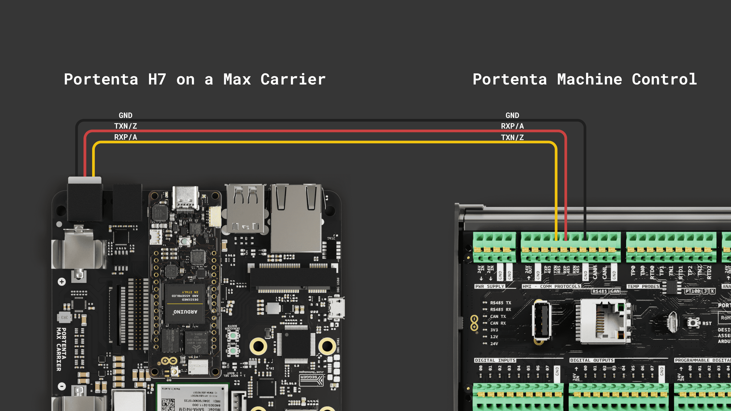
RS-232 Example Code
1/*2 Circuit:3 - Portenta H7 + Max Carrier4 - Arduino Portenta Machine Control (PMC)5 - Connect PMC TXN/Z to Max Carrier RXP/A6 - Connect PMC RXP/A to Max Carrier TXP/Z7
8 created 21 Nov 20239 by Christopher Mendez10*/11
12#include <ArduinoRS485.h>13
14constexpr unsigned long sendInterval{ 1000 };15unsigned long sendNow{ 0 };16int counter = 0;17
18arduino::UART _UART4_{ PA_0, PI_9, NC, NC }; // TX, RX19
20RS485Class rs485{ _UART4_, PA_0, PI_10, PJ_10 }; // UART4, TX, CTS, RTS21
22
23void setup() {24 // Set the Max Carrier Communication Protocols to default config25 RS485init();26 // RS485/RS232 default config is:27 // - RS485 mode28 // - Half Duplex29 // - No A/B and Y/Z 120 Ohm termination enabled30 delay(1000);31 // Enable the RS485/RS232 system32 rs485Enable(true);33 // Enable the RS232 mode34 rs485ModeRS232(true);35 // Specify baudrate for RS232 communication36 rs485.begin(115200);37 // Start in receive mode38 rs485.receive();39}40
41void loop() {42
43 if (rs485.available()) {44 Serial.write(rs485.read());45 }46
47 if (millis() > sendNow) {48 String log = "[";49 log += sendNow;50 log += "] ";51
52 String msg = "hello I'm Max ";53 msg += counter++;54
55 log += msg;56 Serial.println(log);57
58 // Disable receive mode before transmission59 rs485.noReceive();60
61 rs485.beginTransmission();62 rs485.println(msg);63 rs485.endTransmission();64
65 // Re-enable receive mode after transmission66 rs485.receive();67 sendNow = millis() + sendInterval;68 }69}70
71void RS485init() {72 rs485Enable(false);73 rs485ModeRS232(false);74 rs485FullDuplex(false);75 rs485YZTerm(false);76 rs485ABTerm(false);77}78
79void rs485Enable(bool enable) {80 digitalWrite(PC_7, enable ? HIGH : LOW);81}82void rs485ModeRS232(bool enable) {83 digitalWrite(PC_6, enable ? LOW : HIGH);84}85void rs485YZTerm(bool enable) {86 digitalWrite(PG_3, enable ? HIGH : LOW);87}88void rs485ABTerm(bool enable) {89 digitalWrite(PJ_7, enable ? HIGH : LOW);90}91
92void rs485FullDuplex(bool enable) {93 digitalWrite(PA_8, enable ? LOW : HIGH);94 if (enable) {95 // RS485 Full Duplex require YZ and AB 120 Ohm termination enabled96 rs485YZTerm(true);97 rs485ABTerm(true);98 }99}For the Portenta Machine Control, use the library's built-in example code. You can find it on File > Examples > Arduino_PortentaMachineControl > RS232.
Remember that the Portenta Machine Control must be programmed by selecting the
Portenta H7After uploading the code to the Max Carrier and the Machine Control, open both Serial Monitors and you will see the message exchange with a counter and a time stamp.
Support
If you encounter any issues or have questions while working with the Portenta Max Carrier, we provide various support resources to help you find answers and solutions.
Help Center
Explore our Help Center, which offers a comprehensive collection of articles and guides for the Portenta Max Carrier. The Arduino Help Center is designed to provide in-depth technical assistance and help you make the most of your device.
Forum
Join our community forum to connect with other Portenta Max Carrier users, share your experiences, and ask questions. The forum is an excellent place to learn from others, discuss issues, and discover new ideas and projects related to the Portenta Max Carrier.
Contact Us
Please get in touch with our support team if you need personalized assistance or have questions not covered by the help and support resources described before. We're happy to help you with any issues or inquiries about the Portenta Max Carrier.
Suggest changes
The content on docs.arduino.cc is facilitated through a public GitHub repository. If you see anything wrong, you can edit this page here.
License
The Arduino documentation is licensed under the Creative Commons Attribution-Share Alike 4.0 license.