Portenta C33 User Manual
Learn about the hardware and software features of the Arduino® Portenta C33.
Overview
This user manual will provide a comprehensive overview of the Portenta C33 board, covering its major hardware and software elements. With this user manual, you will learn how to set up, configure and use all the main features of the board.
Hardware and Software Requirements
Hardware Requirements
- Portenta C33 (x1)
- USB-C® cable (x1)
- Wi-Fi® W.FL antenna (x1)
Software Requirements
Product Overview
The Portenta C33 is a powerful System-on-Module (SOM) designed for cost-effective Internet of Things (IoT) applications and devices. Based on the R7FA6M5BH2CBG microcontroller from Renesas®, it shares the same form factor as the Portenta H7 board. It is backward-compatible with the MKR and Portenta family shields and carriers through its MKR-styled and High-Density connectors. The Portenta C33 is ideal for a wide range of applications, from smart home devices to connected industrial sensors.
Board Architecture Overview
The Portenta C33 features a robust and efficient architecture that enables it for low-cost, battery-powered, IoT applications and devices.
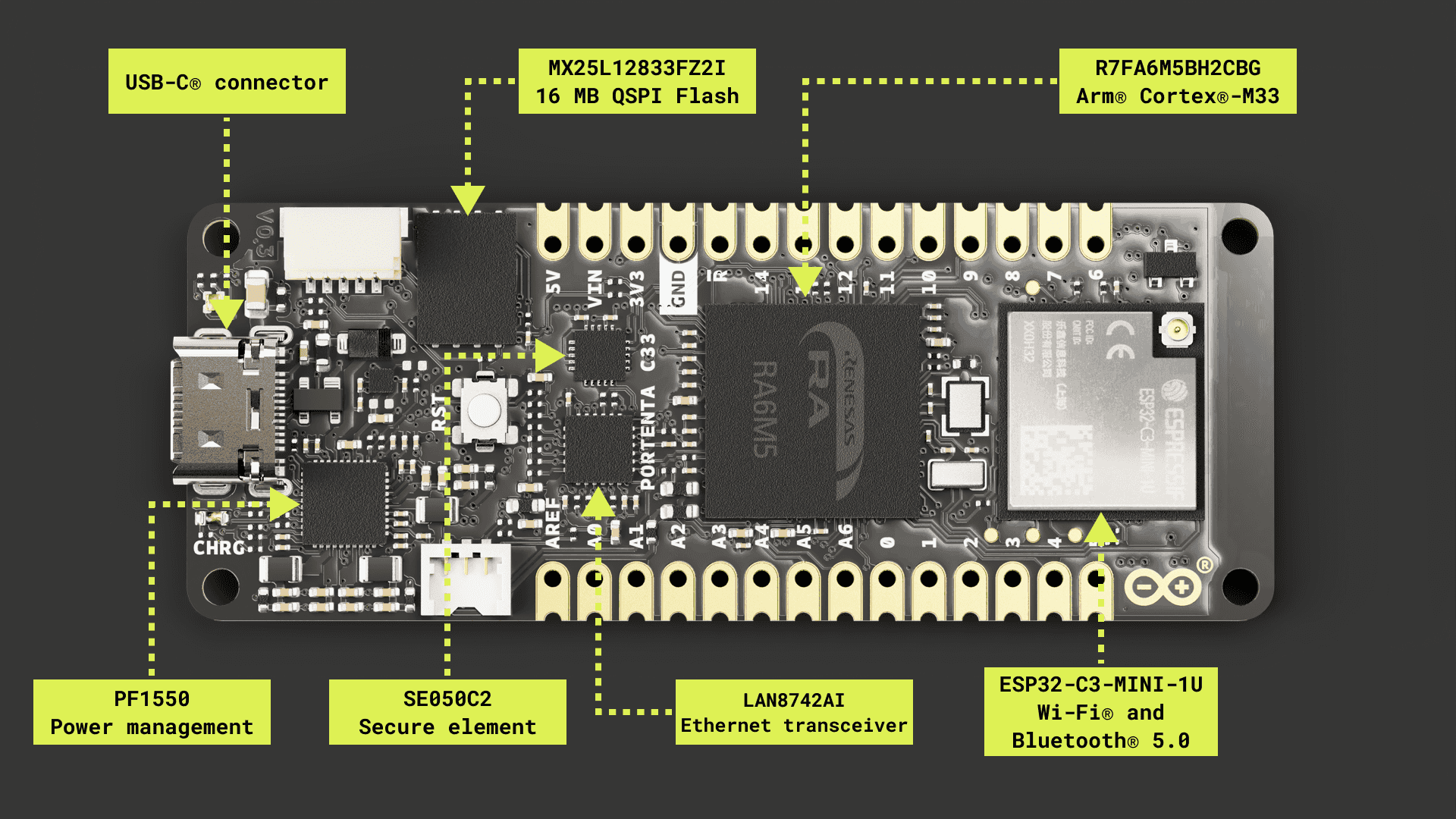
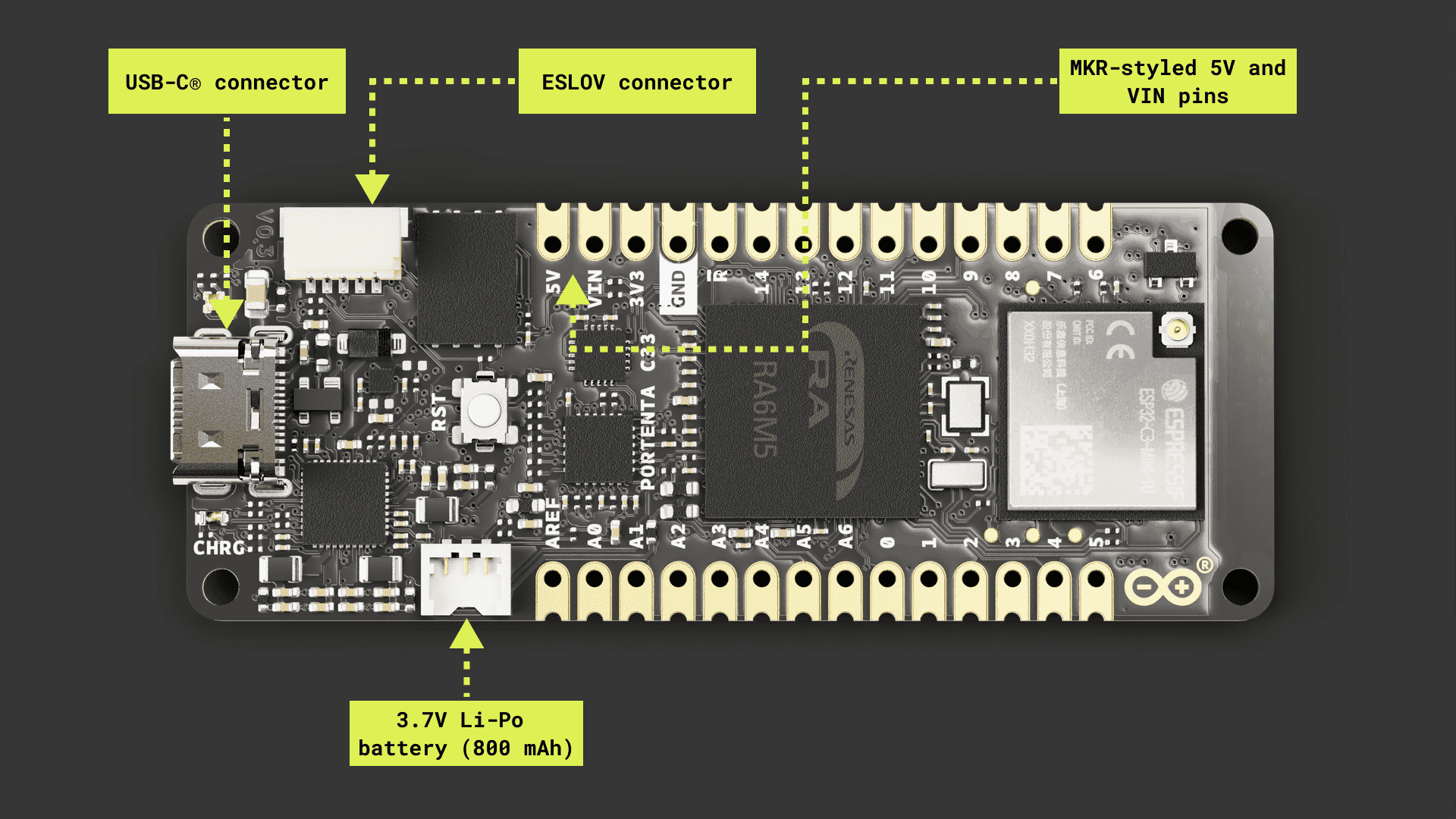
Here is an overview of the board's main components shown in the images above:
- Microcontroller: At the heart of the Portenta C33 is the R7FA6M5BH2CBG, a powerful and versatile SOM from Renesas®. The R7FA6M5BH2CBG is built around a 32-bit Arm® Cortex®-M33 processor running at 200 MHz, with 2 MB of Flash memory and 512 kB of SRAM.
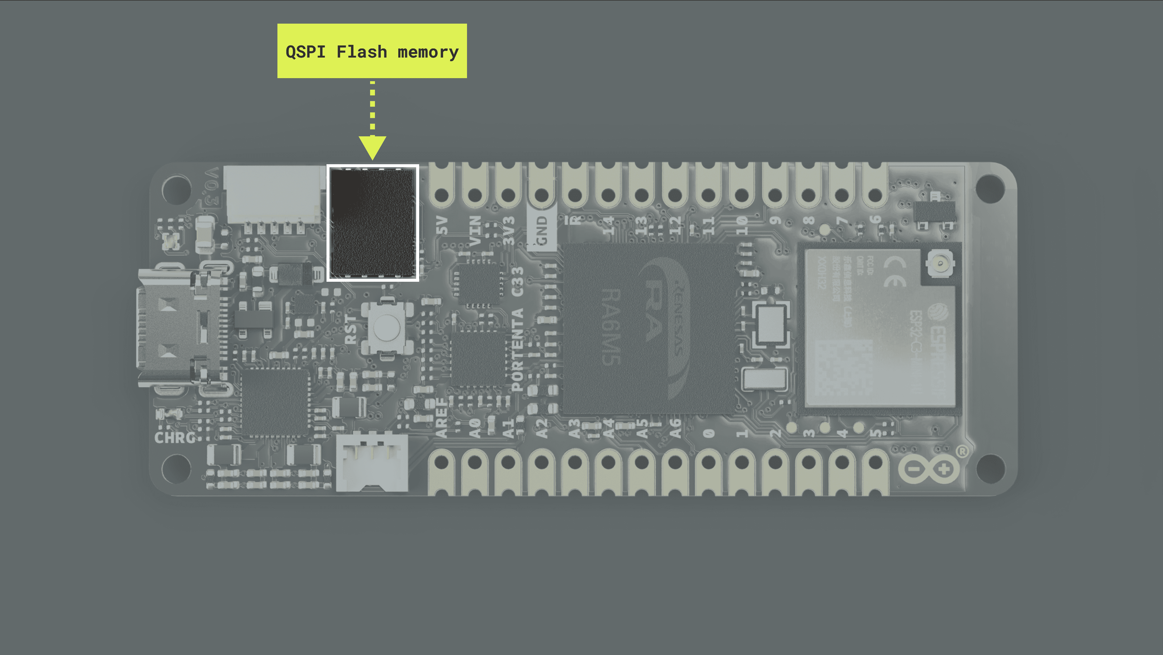
- External memory: The board features an onboard 16 MB QSPI Flash memory.
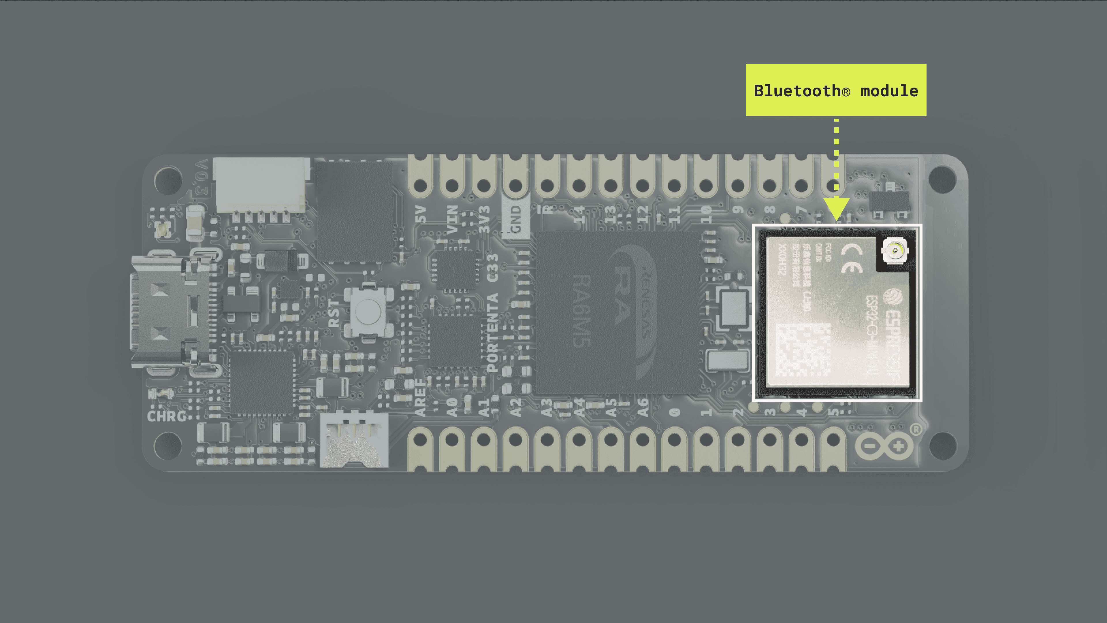
- Wireless connectivity: The board supports 2.4 GHz Wi-Fi® (802.11 b/g/n) and Bluetooth® 5.0, provided by the ESP32-C3-MINI-1U module developed by Espressif Systems®. This high-performance Wi-Fi® and Bluetooth® module allows the Portenta C33 to communicate wirelessly with other devices and systems. Note:
library support is limited to Bluetooth® 4.0 only actually.ArduinoBLE - Ethernet connectivity: The board features an onboard, high-performance 10/100 Mbps Ethernet transceiver accessible through its High-Density connectors.
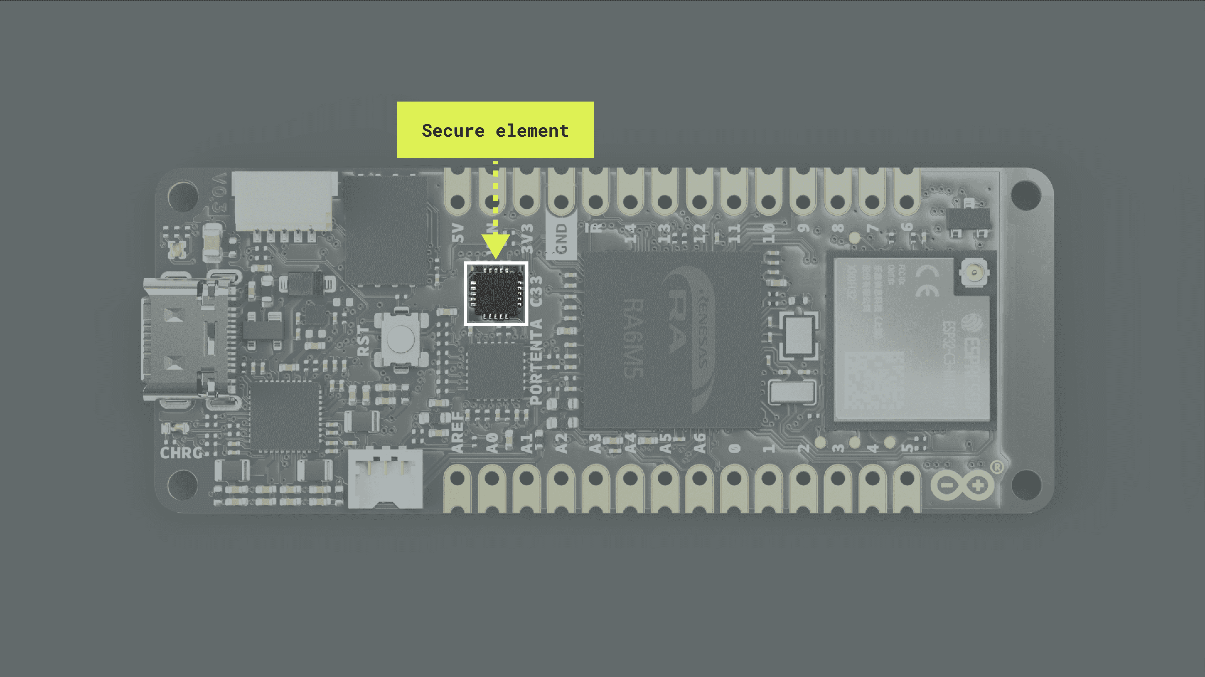
- Security: The board features an onboard ready-to-use secure element, the SE050C2 from NXP®, specifically designed for IoT devices and provides advanced security features.
- USB connectivity: The board features a USB-C port for power and data, which is also accessible through the board's High-Density connectors.
- Power management: The Portenta C33 is designed for low-power operation to meet the demands of always-connected IoT devices. It features a power management integrated circuit (PMIC), the PF1550 from NXP®, designed specifically for low-power, portable, and battery-powered IoT applications.
- Analog and digital peripherals: The board features analog peripherals such as two 8-channel 12-bit analog-to-digital converters (ADC) and two 12-bit digital-to-analog converters (DAC). It also features the following digital peripherals: GPIO (x7), I2C (x1), UART (x4), SPI (x2), PWM (x10), CAN (x2), SPDIF (x1), and SAI (x1).
- Debugging: The board features a JTAG/SWD debug port accessible through its High-Density connectors.
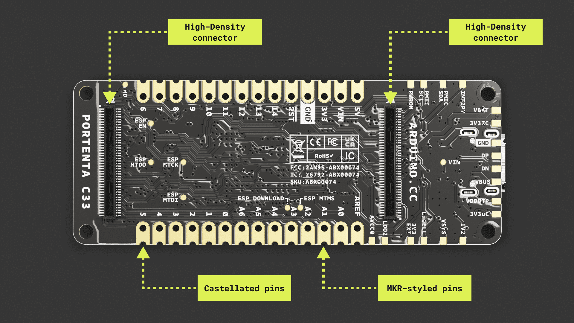
- Surface mount: The castellated pins of the board allow it to be positioned as a surface-mountable module.
- MKR-styled connectors: The MKR-styled connectors of the board make it compatible with all the MKR family boards. 2.54 mm pitch headers can be easily soldered to the board.
Board Core and Libraries
The Arduino Renesas Boards core contains the libraries and examples to work with the Portenta C33's peripherals and onboard components, such as its external QSPI Flash memory and Wi-Fi® and Bluetooth® module. To install the core for the Portenta C33 board, navigate to Tools > Board > Boards Manager or click the Boards Manager icon in the left tab of the IDE. In the Boards Manager tab, search for
renesas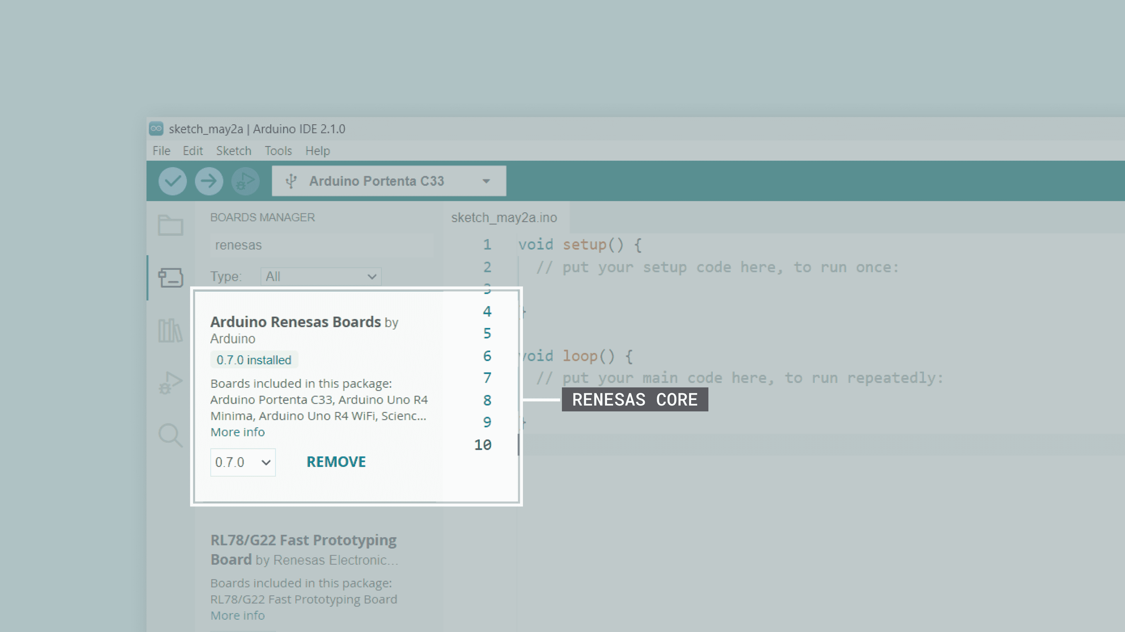
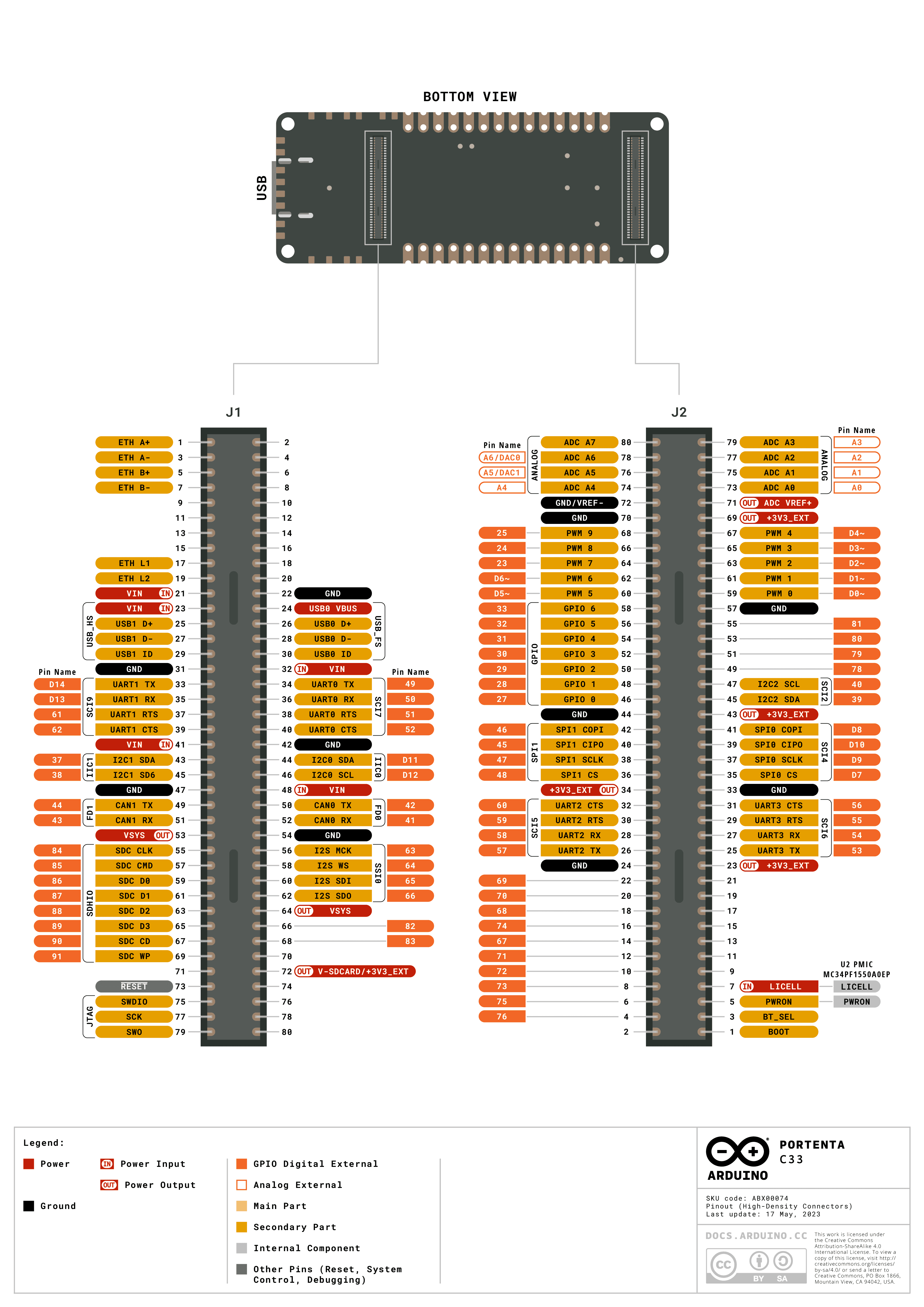
Pinout
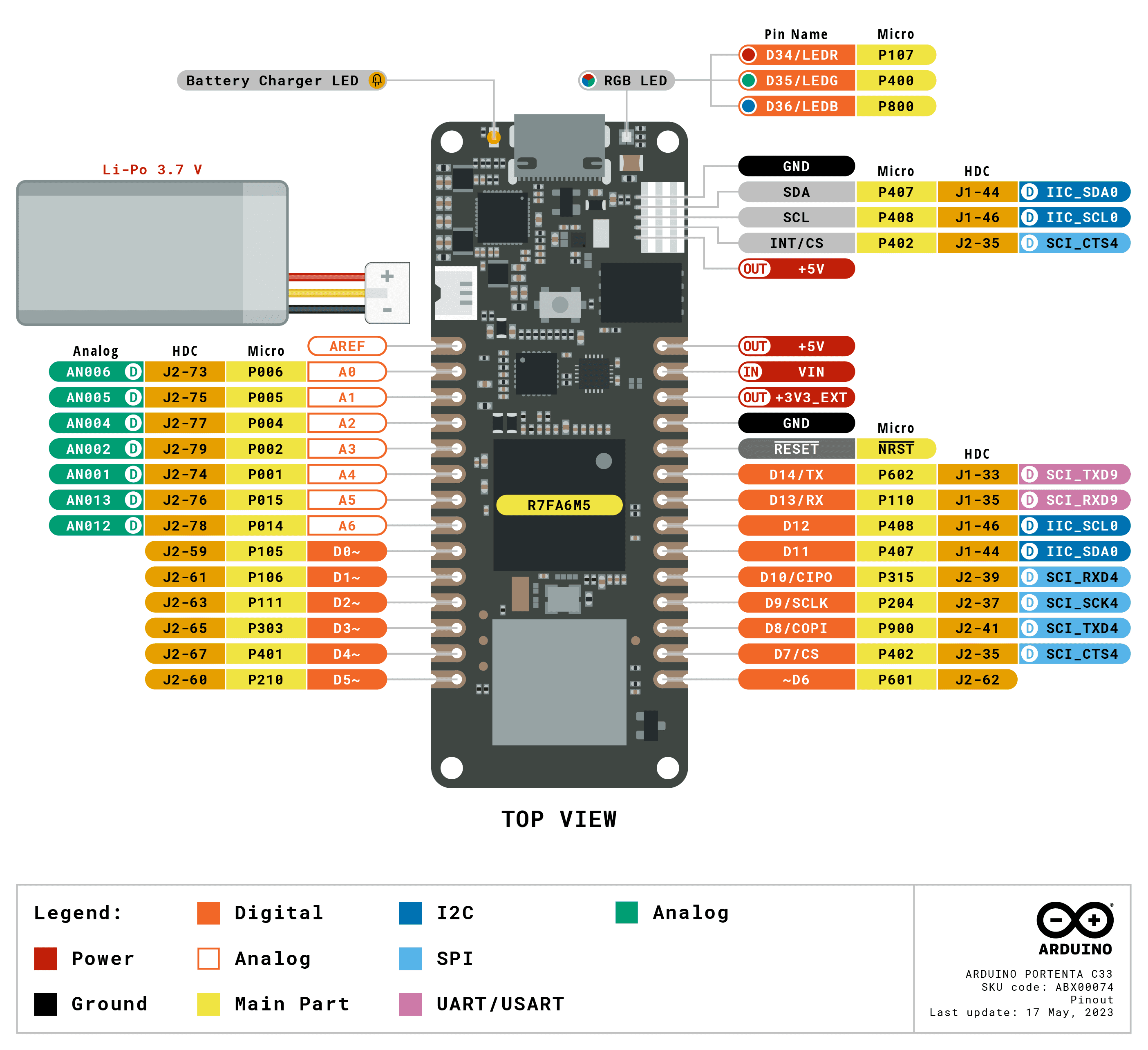
The complete pinout is available and downloadable as PDF from the link below:
Datasheet
The complete datasheet is available and downloadable as PDF from the link below:
Schematics
The complete schematics are available and downloadable as PDF from the link below:
STEP Files
The complete STEP files are available and downloadable from the link below:
First Use
Powering the Board
The Portenta C33 can be powered by the following:
- Using a USB-C® cable (not included).
- Using an external 4.1 to 6 V power supply connected to the
pin located in the MKR-styled connectors pins of the board (please refer to the board pinout section of the user manual).VIN - Using an external 5 V power supply connected to the
pin located in the MKR-styled connectors of the board (please refer to the board pinout section of the user manual).5V - Using a 3.7 V Lithium Polymer (Li-Po) battery connected to the board through the onboard battery connector; the manufacturer part number of the battery connector is BM03B-ACHSS-GAN-TF(LF)(SN), and its matching receptacle manufacturer part number is ACHR-03V-S. The recommended minimum battery capacity for the Portenta C33 is 800 mAh. A Li-Po battery with an integrated NTC thermistor is also recommended for thermal protection.
- Using an Arduino Pro carrier board, such as the Portenta Max Carrier and the Portenta Breakout.
- Using your custom boards to power the board through the board's castellated pins, MKR-styled, or High-Density connectors. Check out the board pinout and its schematic to know more about it.
Hello World Example
Let's program the Portenta C33 with the classic
hello worldBlinkThere are two ways to program this example in the board:
- Navigate to File > Examples > 01.Basics > Blink.
- Copy and paste the code below into a new sketch in the Arduino IDE.
1void setup() {2 // Initialize LED_BUILTIN as an output (this will turn on the LED)3 pinMode(LED_BUILTIN, OUTPUT);4}5
6void loop() {7 // Turn the built-in LED off8 digitalWrite(LED_BUILTIN, HIGH);9 delay(1000);10 // Turn the built-in LED on11 digitalWrite(LED_BUILTIN, LOW);12 delay(1000);13}For the Portenta C33, the
LED_BUILTIN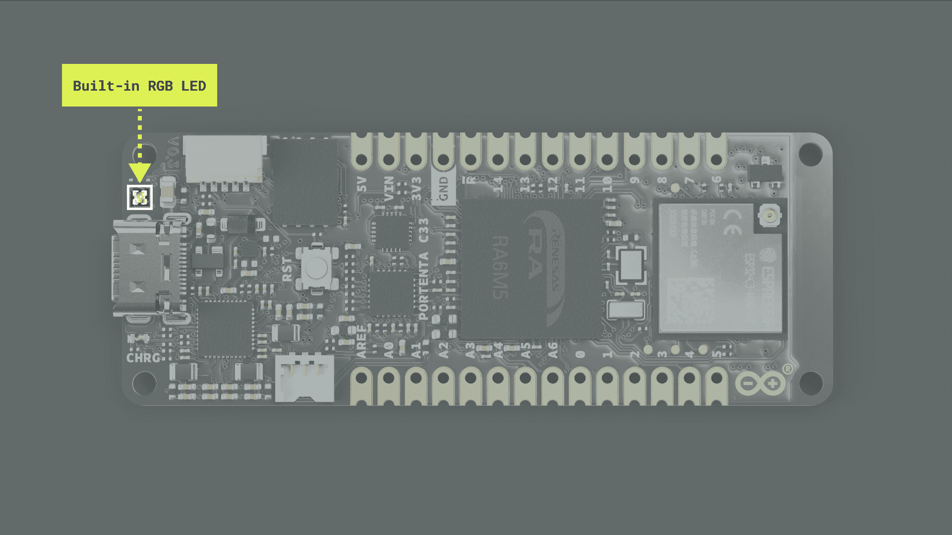
The built-in RGB LED on the Portenta C33 needs to be pulled to ground to make them light up. This means that a voltage level of
on each of their pins will turn the specific color of the LED on, and a voltage level of LOW
will turn them off. Furthermore, invoking the HIGH
instruction pulls the built-in LED LOW, which means it turns it on.pinMode(LED_BUILTIN, OUTPUT)
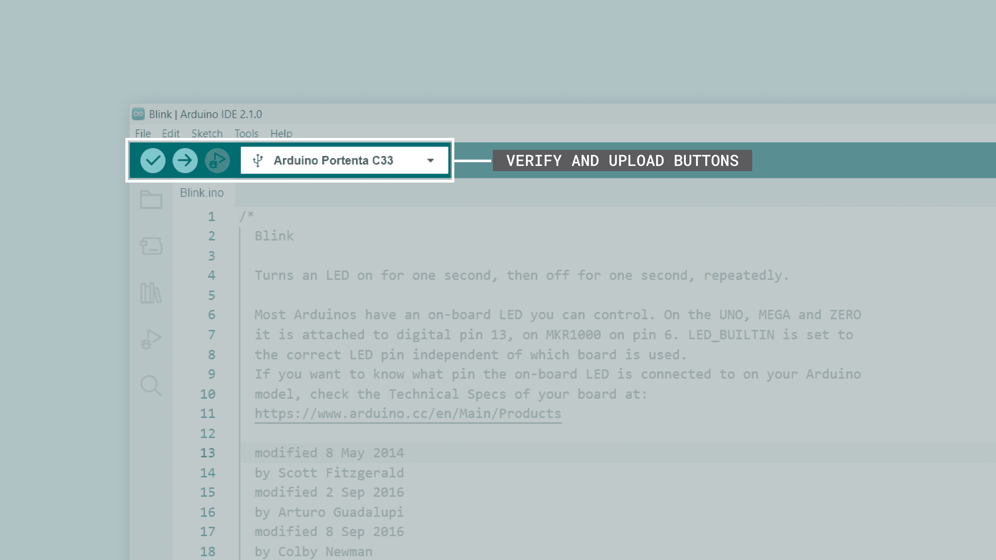
To upload the code to the Portenta C33, click the Verify button to compile the sketch and check for errors; then click the Upload button to program the board with the sketch.
You should see now the green LED of the built-in RGB LED turn on for one second, then off for one second, repeatedly.
Pins
The Portenta C33 has been designed with two types of connectors: the MKR-styled connectors, intended for prototyping and debugging, and the High-Density connectors, intended to be used across Arduino Pro boards or custom boards. The Portenta C33 MKR-styled connectors pinout is shown in the image below:
The Portenta C33 High-Density connectors pinout is shown in the image below:
Analog Pins
The Portenta C33 has eight analog input pins mapped as follows:
| Arduino Pin Mapping | Microcontroller Pin |
|---|---|
| |
| |
| |
| |
| |
| |
| |
| |
The eight analog input pins can be used through the built-in functions of the Arduino programming language (
function).analogRead()
Please refer to the board pinout section of the user manual to find the analog pins on the board:
- MKR-style connectors: pins
,A0
,A1
,A2
,A3
,A4
, andA5
are accessible thought these connectors.A6 - High-Density connectors: pins
,A0
,A1
,A2
,A3
,A4
,A5
, andA6
are accessible thought these connectors.A7
The example code shown below reads the voltage value from a potentiometer connected to
A01// Define the potentiometer pin and variable to store its value2int potentiometerPin = A0;3int potentiometerValue = 0;4
5void setup() {6 // Initialize Serial communication7 Serial.begin(9600);8}9
10void loop() {11 // Read the voltage value from the potentiometer12 potentiometerValue = analogRead(potentiometerPin);13
14 // Print the potentiometer voltage value to the Serial Monitor15 Serial.print("- Potentiometer voltage value: ");16 Serial.println(potentiometerValue);17
18 // Wait for 1000 milliseconds19 delay(1000);20}Digital Pins
The Portenta C33 has 91 digital input/output pins, mapped as described in the following tables. The first 14 digital pins are available through the MKR-styled connectors of the board:
| Arduino Pin Mapping | Pin Functionality | Microcontroller Pin |
|---|---|---|
| GPIO | |
| GPIO | |
| GPIO | |
| GPIO | |
| GPIO | |
| GPIO | |
| GPIO | |
| GPIO/SPI | |
| GPIO/SPI | |
| GPIO/SPI | |
| GPIO/SPI | |
| GPIO/I2C | |
| GPIO/I2C | |
| GPIO/UART | |
| GPIO/UART | |
The following eight digital pins also have analog functionalities; they are available through the MKR-styled and High-Density connectors of the board:
| Arduino Pin Mapping | Pin Functionality | Microcontroller Pin |
|---|---|---|
| GPIO/Analog | |
| GPIO/Analog | |
| GPIO/Analog | |
| GPIO/Analog | |
| GPIO/Analog | |
| GPIO/Analog | |
| GPIO/Analog | |
| GPIO/Analog | |
The following four digital pins are PWM-capable; they are available through the High-Density connectors of the board:
| Arduino Pin Mapping | Pin Functionality | Microcontroller Pin |
|---|---|---|
| GPIO | |
| GPIO | |
| GPIO | |
| GPIO | |
The following seven pins are Interrupt Request (IRQ) capable; they are available through the High-Density connectors of the board:
| Arduino Pin Mapping | Pin Functionality | Microcontroller Pin |
|---|---|---|
| GPIO/IRQ | |
| GPIO/IRQ | |
| GPIO/IRQ | |
| GPIO/IRQ | |
| GPIO/IRQ | |
| GPIO/IRQ | |
| GPIO/IRQ | |
The following three pins are the digital pins used to control the built-in RGB LED of the board:
| Arduino Pin Mapping | Pin Functionality | Microcontroller Pin |
|---|---|---|
| GPIO | |
| GPIO | |
| GPIO | |
The following four digital pins are I2C-capable; they are available through the High-Density connectors of the board:
| Arduino Pin Mapping | Pin Functionality | Microcontroller Pin |
|---|---|---|
| GPIO/I2C | |
| GPIO/I2C | |
| GPIO/I2C | |
| GPIO/I2C | |
The following four digital pins are CAN-capable; they are available through the High-Density connectors of the board:
| Arduino Pin Mapping | Pin Functionality | Microcontroller Pin |
|---|---|---|
| GPIO/CAN RX | |
| GPIO/CAN TX | |
| GPIO/CAN1 RX | |
| GPIO/CAN1 TX | |
The following four digital pins are SPI-capable; they are available through the High-Density connectors of the board:
| Arduino Pin Mapping | Pin Functionality | Microcontroller Pin |
|---|---|---|
| GPIO/MISO1 | |
| GPIO/MOSI1 | |
| GPIO/SCLK1 | |
| GPIO/CS1 | |
The following 14 digital pins are UART-capable; they are available through the High-Density connectors of the board:
| Arduino Pin Mapping | Pin Functionality | Microcontroller Pin |
|---|---|---|
| GPIO/TX2 | |
| GPIO/RX2 | |
| GPIO/RTS2 | |
| GPIO/CTS2 | |
| GPIO/TX3 | |
| GPIO/RX3 | |
| GPIO/RTS3 | |
| GPIO/CTS3 | |
| GPIO/TX4 | |
| GPIO/RX4 | |
| GPIO/RTS4 | |
| GPIO/CTS4 | |
| GPIO/RTS0 | |
| GPIO/CTS0 | |
The following four digital pins are SSI-capable; they are available through the High-Density connectors of the board:
| Arduino Pin Mapping | Pin Functionality | Microcontroller Pin |
|---|---|---|
| GPIO/SSI CK | |
| GPIO/SSI WS | |
| GPIO/SSI SDI | |
| GPIO/SSI SDO | |
The following 17 digital pins are generic GPIO pins; they are available through the High-Density connectors of the board:
| Arduino Pin Mapping | Pin Functionality | Microcontroller Pin |
|---|---|---|
| GPIO | |
| GPIO | |
| GPIO | |
| GPIO | |
| GPIO | |
| GPIO | |
| GPIO | |
| GPIO | |
| GPIO | |
| GPIO | |
| GPIO | |
| GPIO | |
| GPIO | |
| GPIO | |
| GPIO | |
| GPIO | |
| GPIO | |
The last eight digital pins are SD-card-capable; they are available through the High-Density connectors of the board:
| Arduino Pin Mapping | Pin Functionality | Microcontroller Pin |
|---|---|---|
| GPIO/SDHI CLK | |
| GPIO/SDHI CMD | |
| GPIO/SDHI D0 | |
| GPIO/SDHI D1 | |
| GPIO/SDHI D2 | |
| GPIO/SDHI D3 | |
| GPIO/SDHI CD | |
| GPIO/SDHI WP | |
The basic functionality of the Portenta C33's digital pins can be implemented through the built-in functions of the Arduino programming language. The configuration of a digital pin is done in the
setup()pinMode()1// Pin configured as an input2pinMode(pin, INPUT);3
4// Pin configured as an output5pinMode(pin, OUTPUT);6
7// Pin configured as an input, internal pull-up resistor enabled8pinMode(pin, INPUT_PULLUP);The state of a digital pin, configured as an input, can be read using the built-in function
as shown below:digitalRead()
1// Reads pin state, stores value in state variable2state = digitalRead(pin);The state of a digital pin, configured as an output, can be changed using the built-in function
as shown below:digitalWrite()
1// Set pin on2digitalWrite(pin, HIGH);3
4// Set pin off5digitalWrite(pin, LOW);The example code shown below uses digital pin
321// Define button and LED pin2int buttonPin = 2;3int ledPin = 3;4
5// Variable to store the button state6int buttonState = 0;7
8void setup() {9 // Configure button and LED pins10 pinMode(buttonPin, INPUT_PULLUP);11 pinMode(ledPin, OUTPUT);12
13 // Initialize Serial communication14 Serial.begin(9600);15}16
17void loop() {18 // Read the state of the button19 buttonState = digitalRead(buttonPin);20
21 // If the button is pressed, turn on the LED and print its state to the Serial Monitor22 if (buttonState == LOW) {23 digitalWrite(ledPin, HIGH);24 Serial.println("- Button is pressed. LED is on.");25 } else {26 // If the button is not pressed, turn off the LED and print to the Serial Monitor27 digitalWrite(ledPin, LOW);28 Serials.println("- Button is not pressed. LED is off.");29 }30
31 // Wait for 1000 milliseconds32 delay(1000);33}PWM Pins
The Portenta C33 has 10 digital pins with PWM functionality, mapped as follows:
| Arduino Pin Mapping | Microcontroller Pin |
|---|---|
| |
| |
| |
| |
| |
| |
| |
| |
| |
| |
| |
| |
| |
| |
The 10 PWM pins can be used through the built-in (
function) of the Arduino programming language. analogWrite()
Please refer to the board pinout section of the user manual to find them on the board.
- MKR-styled connectors: pins
,0
,1
,2
,3
,4
, and5
are accessible through these connectors.6 - High-Density connectors: pins
,0
,1
,2
,3
,4
,5
,7
,8
,9
,23
,24
, and25
are accessible through these connectors.26
The example code shown below uses digital pin
91// Define the LED pin, brightness, and fade amount variables2int brightness = 0;3int fadeAmount = 5;4
5void setup() {6 // Configure the LED pin as an output7 pinMode(LEDG, OUTPUT);8}9
10void loop() {11 // Set the brightness of the LED12 analogWrite(LEDG, brightness);13
14 // Update the brightness value15 brightness += fadeAmount;16
17 // Reverse the fade direction when reaching the limits18 if (brightness <= 0 || brightness >= 255) {19 fadeAmount = -fadeAmount;20 }21
22 // Wait for 30 milliseconds23 delay(30);24}You should now see the built-in RGB LED's green LED fade in and then fade out repeatedly.
Actuators
This user manual section covers the Portenta C33 built-in actuators, showing their main hardware and software characteristics.
RGB LED
The Portenta C33 features a built-in RGB LED that can be used as a visual feedback indicator for the user.
The built-in RGB LED can be accessed through the following macro definitions:
| Built-in LED | Macro Definition |
|---|---|
| Red LED | |
| Blue LED | |
| Green LED | |
The built-in RGB LED on the Portenta C33 must be pulled to ground to make it light up. This means that a voltage level of
on each of their pins will turn the specific color of the LED on, and a voltage level of LOW
will turn them off. Furthermore, invoking the HIGH
instruction pulls the built-in LED LOW, which means it turns it on.pinMode(LED_BUILTIN, OUTPUT)
The following example code blinks each of the LEDs at an interval of 500 ms:
1void setup() {2 // Initialize LEDR, LEDG and LEDB as outputs3 pinMode(LEDR, OUTPUT);4 pinMode(LEDG, OUTPUT);5 pinMode(LEDB, OUTPUT);6}7
8void loop() {9 // Turn on the built-in red LED and turn off the rest10 digitalWrite(LEDR, LOW);11 digitalWrite(LEDG, HIGH);12 digitalWrite(LEDB, HIGH);13 delay(500);14 // Turn on the built-in green LED and turn off the rest15 digitalWrite(LEDR, HIGH);16 digitalWrite(LEDG, LOW);17 digitalWrite(LEDB, HIGH);18 delay(500);19 // Turn on the built-in blue LED and turn off the rest20 digitalWrite(LEDR, HIGH);21 digitalWrite(LEDG, HIGH);22 digitalWrite(LEDB, LOW);23 delay(500);24}You should now see the built-in RGB LED blinking each of its LEDs repeatedly.
Communication
This section of the user manual covers the different communication protocols that are supported by the Portenta C33 board, including the Serial Peripheral Interface (SPI), Inter-Integrated Circuit (I2C), Universal Asynchronous Receiver-Transmitter (UART), and Wi-Fi®; JTAG interface and communication via the onboard ESLOV connector is also explained in this section.
The Portenta C33 features dedicated pins for each communication protocol, accessible through the MKR-styled connectors and the High-Density connectors, making connecting and communicating with different components, peripherals, and sensors easy.
SPI
The Portenta C33 supports SPI communication via two dedicated ports named
SPI0SPI1| Arduino Pin Mapping | Microcontroller Pin |
|---|---|
| |
| |
| |
| |
| |
| |
| |
| |
Please refer to the board pinout section of the user manual to find them on the board. Include the
library at the top of your sketch to use the SPI communication protocol. The SPI library provides functions for SPI communication:SPI
1#include <SPI.h>In the
setup()CS1void setup() {2 // Set the chip select pin as output3 pinMode(SS, OUTPUT);4
5 // Pull the CS pin HIGH to unselect the device6 digitalWrite(SS, HIGH);7
8 // Initialize the SPI communication9 SPI.begin();10}To transmit data to an SPI-compatible device, you can use the following commands:
1// Replace with the target device's address2byte address = 0x00;3
4// Replace with the value to send5byte value = 0xFF;6
7// Pull the CS pin LOW to select the device8digitalWrite(SS, LOW);9
10// Send the address11SPI.transfer(address);12
13// Send the value14SPI.transfer(value);15
16// Pull the CS pin HIGH to unselect the device17digitalWrite(SS, HIGH);I2C
The Portenta C33 supports I2C communication, which allows data transmission between the board and other I2C-compatible devices. There are three available I2C ports in the Portenta C33:
I2C0I2C1I2C2| Arduino Pin Mapping | Microcontroller Pin |
|---|---|
| |
| |
| |
| |
| |
| |
To locate these pins on the board, please refer to the board pinout section of the user manual. The
SDA0SCL0System integrators can use the Portenta C33's High-Density connectors to expand the signals of the board to a custom-designed daughter board or carrier. Below is the I2C pins mapping on the board's High-Density connectors and shared resources:
| HD Connector | Interface | Pins | Status | Shared Peripherals |
|---|---|---|---|---|
| J1 | | 43-45 | Free | - |
| J2 | | 44-46 | Free | - |
| J2 | | 45-47 | Free | - |
The status column indicates the current status of the pins. "Free" means the pins are not in use by another resource or peripheral of the board and are available for usage, while "Shared" means the pins are used by one or several resources or peripherals of the board.
To use I2C communication, include the
library at the top of your sketch. The Wire
Wire1#include <Wire.h>In the
setup()1// Initialize the I2C communication2Wire.begin();To transmit data to an I2C-compatible device, you can use the following commands:
1// Replace with the target device's I2C address2byte deviceAddress = 0x1;3
4// Replace with the appropriate instruction byte5byte instruction = 0x00;6
7// Replace with the value to send8byte value = 0xFF;9
10// Begin transmission to the target device11Wire.beginTransmission(deviceAddress);12
13// Send the instruction byte14Wire.write(instruction);15
16// Send the value17Wire.write(value);18
19// End transmission20Wire.endTransmission();To read data from an I2C-compatible device, you can use the
requestFrom()read()1// The target device's I2C address2byte deviceAddress = 0x1;3
4// The number of bytes to read5int numBytes = 2;6
7// Request data from the target device8Wire.requestFrom(deviceAddress, numBytes);9
10// Read while there is data available11while (Wire.available()) {12 byte data = Wire.read();13}UART
The Portenta C33 supports UART communication. The pins used in the Portenta C33 for the UART communication protocol are the following:
| Arduino Pin Mapping | Microcontroller Pin |
|---|---|
| |
| |
| |
| |
| |
| |
| |
| |
| |
| |
Please refer to the board pinout section of the user manual to find them on the board. The built-in (Serial) library functions can use the UART pins.
To begin with UART communication, you'll need to configure it first. In the
setup()1// Start UART communication at 9600 baud2Serial.begin(9600);To read incoming data, you can use a
while()Serial.available()Serial.read()1// Variable for storing incoming data2String incoming = "";3
4void loop() {5 // Check for available data and read individual characters6 while (Serial.available()) {7 // Allow data buffering and read a single character8 delay(2);9 char c = Serial.read();10
11 // Check if the character is a newline (line-ending)12 if (c == '\n') {13 // Process the received data14 processData(incoming);15
16 // Clear the incoming data string for the next message17 incoming = "";18 } else {19 // Add the character to the incoming data string20 incoming += c;21 }22 }23}To transmit data to another device via UART, you can use the
Serial.write()1// Transmit the string "Hello world!2Serial.write("Hello world!");You can also use the
Serial.print()Serial.println()1// Transmit the string "Hello world!"2Serial.print("Hello world!");3
4// Transmit the string "Hello world!" followed by a newline character5Serial.println("Hello world!");Wi-Fi®
The Portenta C33 board features an onboard Wi-Fi® module, the ESP32-C3-MINI-1U module from Espressif Systems®. The ESP32-C3-MINI-1U is a low-power, highly integrated Wi-Fi® and Bluetooth® System-on-Chip (SoC) solution designed for many IoT applications.

Some of the key capabilities of the ESP32-C3-MINI-1U module are the following:
- Wi-Fi® and Bluetooth® connectivity: The module supports 2.4 GHz Wi-Fi® (802.11 b/g/n) and Bluetooth® 5.0 connectivity.
library support is limited to Bluetooth® 4.0 at this time.ArduinoBLE - CPU and memory: It contains a 32-bit RISC-V single-core processor with a clock speed of up to 160 MHz. The chip also has 400 KB of SRAM and 384 KB of ROM.
- Security features: It supports various security features, including secure boot, flash encryption, and cryptographic hardware acceleration.
- Low-power operation: It supports multiple power modes for different low-power applications, making it suitable for battery-powered devices.
The Arduino Renesas Core has a built-in library that lets you use the onboard Wi-Fi® module, the
WiFiC3Always connect your board's Wi-Fi® module with its W.FL antenna (included with your board) to avoid damaging it.
The code below showcases how to connect to a Wi-Fi® network, check Wi-Fi® status, connect to a server, send HTTP requests, and receive and print HTTP responses, which are common tasks for an IoT device.
1/**2 Web Client (Wi-Fi version)3 Name: WiFiWebClient.ino4 Purpose: This sketch connects to a website via Wi-Fi5
6 @author Arduino Team7 @version 2.0 31/05/128*/9
10// Include the necessary libraries for Wi-Fi management and HTTP communication11#include "WiFiC3.h"12#include "WiFiClient.h"13#include "IPAddress.h"14#include "arduino_secrets.h"15
16// Define the credentials of the Wi-Fi network to connect to17char ssid[] = SECRET_SSID; // Network SSID18char pass[] = SECRET_PASS; // Network password19
20// Define a variable for storing the status of the Wi-Fi connection21int status = WL_IDLE_STATUS;22
23// Define the server to which we'll connect24// This can be an IP address or a URL25char server[] = "www.google.com";26
27// Initialize the Wi-Fi client object28// This will be used to interact with the server29WiFiClient client;30
31void setup() {32 // Begin serial communication at a baud rate of 11520033 Serial.begin(115200);34
35 // Wait for the serial port to connect36 // This is necessary for boards that have native USB37 while (!Serial) {}38
39 // Check for the onboard Wi-Fi module40 // If the module isn't found, halt the program41 if (WiFi.status() == WL_NO_MODULE) {42 Serial.println("- Communication with Wi- Fi module failed!");43 while (true);44 }45
46 // Check if the Wi-Fi module's firmware is up to date47 String fv = WiFi.firmwareVersion();48 if (fv < WIFI_FIRMWARE_LATEST_VERSION) {49 Serial.println("- Please upgrade the firmware!");50 }51
52 // Attempt to connect to the defined Wi-Fi network53 // Wait for the connection to be established54 while (status != WL_CONNECTED) {55 Serial.print("- Attempting to connect to SSID: ");56 Serial.println(ssid);57 status = WiFi.begin(ssid, pass);58 delay(10000); 59 }60
61 // Print the Wi-Fi connection status62 printWifiStatus(); 63
64 // Attempt to connect to the server at port 80 (the standard port for HTTP).65 // If the connection is successful, print a message and send a HTTP GET request.66 // If the connection failed, print a diagnostic message.67 Serial.println("\n- Starting connection to server...");68 if (client.connect(server, 80)) {69 Serial.println("- Connected to server!");70 client.println("GET /search?q=arduino HTTP/1.1");71 client.println("Host: www.google.com");72 client.println("Connection: close");73 client.println();74 } else {75 Serial.println("- Connection failed!");76 }77}78
79/**80 Reads data from the client while there's data available81
82 @param none83 @return none84*/85void read_response() {86 uint32_t received_data_num = 0;87 while (client.available()) {88
89 // Actual data reception90 char c = client.read();91
92 // Print data to serial port93 Serial.print(c);94
95 // Wrap data to 80 columns96 received_data_num++;97 if (received_data_num % 80 == 0) {98 Serial.println();99 }100 }101}102
103void loop() {104 // Read and print the server's response105 read_response();106
107 // If the server has disconnected, disconnect the client and halt the program108 if (!client.connected()) {109 Serial.println();110 Serial.println("- Disconnecting from server...");111 client.stop();112 while (true);113 }114}115
116/**117 Prints data from the Wi-Fi connection status118
119 @param none120 @return none121*/122void printWifiStatus() {123 // Print network SSID124 Serial.print("- SSID: ");125 Serial.println(WiFi.SSID());126
127 // Print board's IP address128 IPAddress ip = WiFi.localIP();129 Serial.print("- IP Address: ");130 Serial.println(ip);131
132 // Print signal strength133 long rssi = WiFi.RSSI();134 Serial.print("- Signal strength (RSSI):");135 Serial.print(rssi);136 Serial.println(" dBm");137}First, the necessary libraries are included:
- The
andWiFiC3.h
are included at the start, those libraries contains the functionalities required to communicate via Wi-Fi®.WiFiClient.h - The SSID and password for the Wi-Fi® network are defined.
Then, the server is defined (
www.google.comNext, in the
setup()- The serial port is initialized at a baud rate of 115200.
- The sketch checks for Wi-Fi® module availability and its firmware version, then attempts to connect to the Wi-Fi® network with the defined SSID and password. If the connection is successful, it prints the Wi-Fi® status and attempts to connect to the defined server. If the server connection is successful, it sends a GET request.
- The
function reads data from the client while there's data available. It wraps the data to 80 columns and prints it to the IDE's Serial Monitor.read_reponse()
Finally, in the loop() function:
- The
function is called to read any available data. If the server is disconnected, it disconnects the client and enters an infinite loop, halting the sketch.read_response() - The
function prints the connected network SSID, the IP address of the board, and the signal strength (RSSI) to the IDE's Serial Monitor.printWifiStatus()
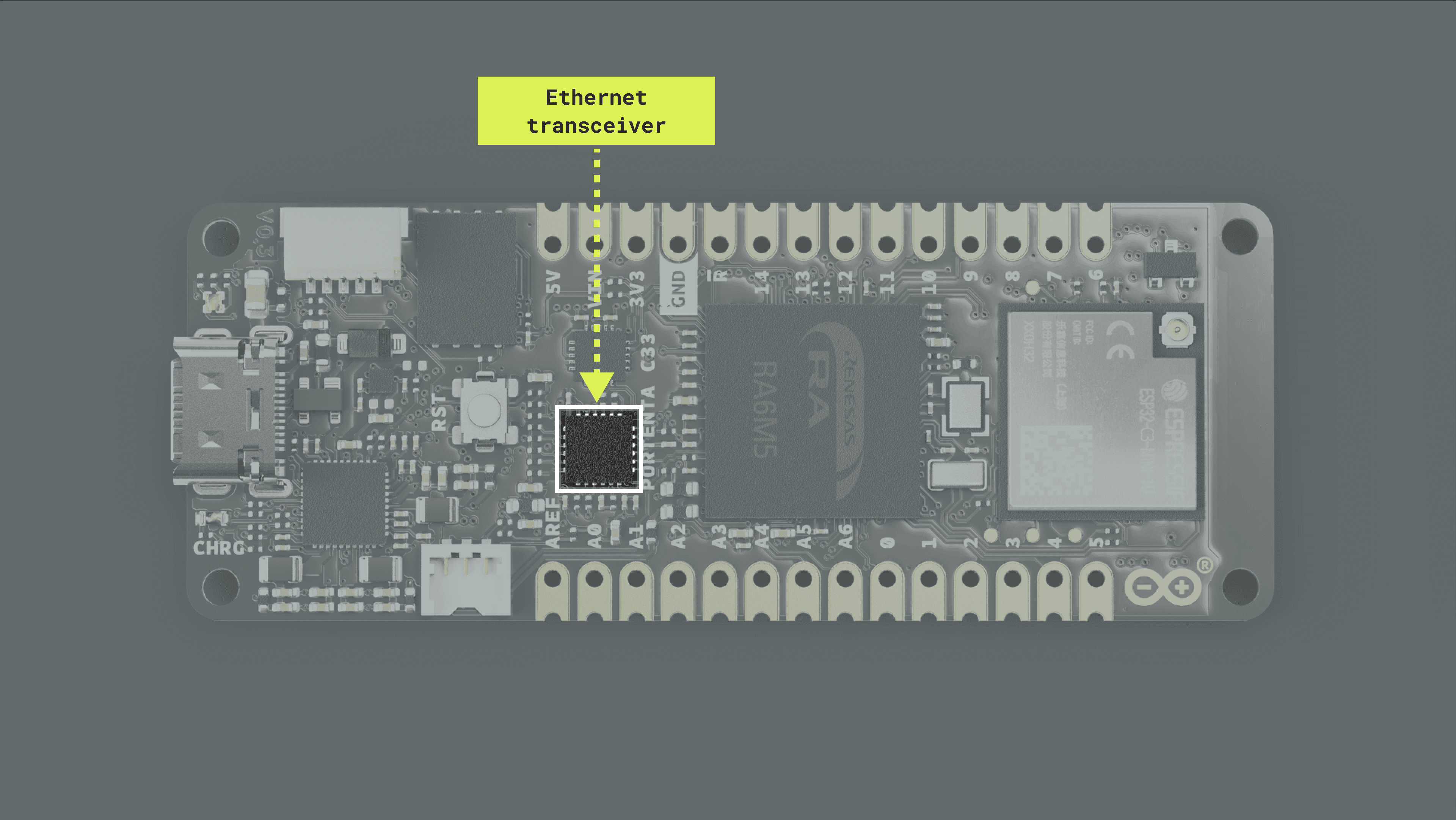
Ethernet
The Portenta C33 board features an Ethernet physical layer (PHY) transceiver, the LAN8742AI from Microchip®. The LAN8742AI is a low-power 10BASE-T/100BASE-TX physical layer (PHY) transceiver. This device is responsible for transmitting and receiving data over an Ethernet connection. The transceiver complies with the IEEE 802.3 and 802.3u standards and supports communication with an Ethernet MAC through a standard RMII interface.
Some of the key capabilities of the LAN8742AI are the following:
- Speed and duplex mode: It can operate at 10 Mbps (10BASE-T) or 100 Mbps (100BASE-TX). It also features auto-negotiation, which means it can automatically determine the best speed and duplex mode for communication.
- HP Auto-MDIX: This feature allows you to use a straight-through or crossover Ethernet cable.
- Wake on LAN (WoL): The device can be programmed to detect certain types of packets and trigger an interrupt.
- Cable diagnostics: The transceiver can detect issues with the Ethernet cable and determine its location.
The Arduino Renesas Core has a built-in library that lets you use the onboard Ethernet PHY transceiver right out of the box, the
EthernetC331/**2 Web Client (Ethernet version)3 Name: WebClient.ino4 Purpose: This sketch connects to a website via Ethernet5
6 @author Arduino Team7 @version 4.0 01/06/188*/9
10// Include the Ethernet library11#include <EthernetC33.h>12
13// Define the server to which we'll connect14// This can be an IP address or a URL15char server[] = "www.google.com";16
17// Set a static IP address to use if the DHCP fails to assign one automatically18IPAddress ip(10, 130, 22, 84);19
20// Initialize the Ethernet client object21// This will be used to interact with the server22EthernetClient client;23
24void setup() {25 // Begin serial communication at a baud rate of 11520026 Serial.begin(115200);27
28 // Wait for the serial port to connect29 // This is necessary for boards that have native USB30 while (!Serial);31
32 // Attempt to start Ethernet connection via DHCP33 // If DHCP failed, print a diagnostic message34 if (Ethernet.begin() == 0) {35 Serial.println("- Failed to configure Ethernet using DHCP!");36
37 // Try to configure Ethernet with the predefined static IP address38 Ethernet.begin(ip);39 }40
41 delay(2000);42
43 // Attempt to connect to the server at port 80 (the standard port for HTTP).44 // If the connection is successful, print a message and send a HTTP GET request.45 // If the connection failed, print a diagnostic message.46 Serial.println("- Connecting...");47 if (client.connect(server, 80)) {48 Serial.println("- Connected!");49 client.println("GET /search?q=arduino HTTP/1.1");50 client.println("Host: www.google.com");51 client.println("Connection: close");52 client.println();53 } else {54 Serial.println("- Connection failed!");55 }56}57
58/**59 Reads data from the client while there's data available60
61 @param none62 @return none63*/64void read_request() {65 uint32_t received_data_num = 0;66 while (client.available()) {67
68 // Actual data reception69 char c = client.read();70
71 // Print data to serial port72 Serial.print(c);73
74 // Wrap data to 80 columns75 received_data_num++;76 if (received_data_num % 80 == 0) {77 Serial.println();78 }79 }80}81
82void loop() {83 // Read data from the client84 read_request();85
86 // If there's data available from the server, read it and print it to the Serial Monitor87 while (client.available()) {88 char c = client.read();89 Serial.print(c);90 }91
92 // If the server has disconnected, disconnect the client and stop93 if (!client.connected()) {94 Serial.println();95 Serial.println("- Disconnecting...");96 client.stop();97
98 // Halt the sketch by entering an infinite loop99 while (true);100 }101}First, the necessary libraries are included:
- The
library which contains the functionality required to communicate via Ethernet is included in the beginning.EthernetC33
Then, the server is defined, which is
www.google.comThe static IP address which will be used if the DHCP fails to assign an IP address is set.
The Ethernet client is initialized with the server's IP address and port.
Next, in the
setup()- The serial port is initialized at a baud rate of 115200.
- An Ethernet connection is attempted; if the DHCP configuration fails, the sketch tries to configure the connection using the static IP address defined before. The usage of a DNS server depends also on the success of the DHCP configuration.
- If the DNS server is used, it connects to the server using the server name; otherwise, it uses the server IP address. If the connection is successful, it sends a
request to the server. If not, it outputs an error message to the IDE's Serial Monitor.HTTP GET - The
function reads data from the client while there's data available. It wraps the data to 80 columns and prints it to the IDE's Serial Monitor.read_request()
Finally, in the
loop()- The
function is called to read any available data. If the server is disconnected, it disconnects the client and enters an infinite loop, halting the sketch.read_request()
Bluetooth®
The Portenta C33 board features an onboard Bluetooth® module, the ESP32-C3-MINI-1U module from Espressif Systems®. The ESP32-C3-MINI-1U is a low-power, highly integrated Wi-Fi® and Bluetooth® System-on-Chip (SoC) solution designed for many IoT applications.
Always connect your board's Bluetooth® module with its W.FL antenna (included with your board) to avoid damaging it.
To enable Bluetooth® communication on the Portenta C33, you can use the
libraryArduinoBLE
ArduinoBLEArduinoBLE1/**2 Portenta_C33_Bluetooth3 Name: Portenta_C33_Bluetooth.ino4 Purpose: Read voltage level from an analog input of the Portenta C335 then maps the voltage reading to a percentage value ranging from 0 to 100.6
7 Then exposes the voltage percentage level using a Custom BLuetooth Service.8
9 @author Arduino Team10 @version 1.1 13/07/2311*/12
13#include <ArduinoBLE.h>14
15// Define the voltage service and its characteristic16BLEService voltageService("1101");17BLEUnsignedCharCharacteristic voltageLevelChar("2101", BLERead | BLENotify);18
19
20const int analogPin = A0;21
22/**23 Read voltage level from an analog input of the Portenta C33,24 then maps the voltage reading to a percentage value ranging from 0 to 100.25
26 @param none27 @return the voltage level percentage (int).28*/29
30int readVoltageLevel() {31 int voltage = analogRead(analogPin);32 int voltageLevel = map(voltage, 0, 1023, 0, 100);33 return voltageLevel;34}35
36void setup() {37 // Initialize LEDB as an output38 pinMode(LEDB, OUTPUT);39 digitalWrite(LEDB, HIGH);40
41 Serial.begin(9600);42
43 // Initialize the BLE module44 if (!BLE.begin()) {45 Serial.println("- Starting BLE failed!");46 while (1)47 ;48 }49
50 // Set the local name and advertised service for the BLE module51 BLE.setLocalName("VoltageMonitor");52 BLE.setAdvertisedService(voltageService);53 voltageService.addCharacteristic(voltageLevelChar);54 BLE.addService(voltageService);55
56 // Start advertising the BLE service57 BLE.advertise();58 Serial.println("- Bluetooth device active, waiting for connections...");59}60
61void loop() {62 // Check for incoming BLE connections63 BLEDevice central = BLE.central();64
65 // If a central device is connected66 if (central) {67 Serial.print("- Connected to device: ");68 Serial.println(central.address());69
70 // Set the LED color to solid blue when connected71 digitalWrite(LEDB, LOW);72
73 // While the central device is connected74 while (central.connected()) {75 // Read the voltage level and update the BLE characteristic with the level value76 int voltageLevel = readVoltageLevel();77
78 Serial.print("- Voltage level is: ");79 Serial.println(voltageLevel);80 voltageLevelChar.writeValue(voltageLevel);81
82 delay(200);83 }84 }85
86 // The LED blinks when bluetooth® is not connected to an external device87 digitalWrite(LEDB, HIGH);88 delay(200);89 digitalWrite(LEDB, LOW);90 delay(200);91
92 Serial.print("- BLE not connected: ");93 Serial.println(central.address());94}The example code shown above creates a Bluetooth® Low Energy service and characteristic for transmitting a voltage value read by one of the analog pins of the Portenta C33 to a central device.
- The code begins by importing all the necessary libraries and defining the Bluetooth® Low Energy service and characteristics.
- In the setup() function, the code initializes the Portenta C33 board and sets up the Bluetooth® Low Energy service and characteristics. Then, it begins advertising the defined Bluetooth® Low Energy service.
- A Bluetooth® Low Energy connection is constantly verified in the loop() function; when a central device connects to the Portenta C33, its built-in blue LED is turned into a solid blue. The code then enters into a loop that constantly reads the voltage level from an analog input and maps it to a percentage value between 0 and 100. The voltage level is printed to the Serial Monitor and transmitted to the central device over the defined Bluetooth® Low Energy characteristic.
JTAG
The Portenta C33 board features a JTAG/SWD debug port accessible through its High-Density connectors. The pins used for the JTAG/SWD debug port are the following:
| Functionality | Microcontroller Pin |
|---|---|
| |
| |
| |
You can use a Portenta Breakout with your Portenta C33 board to easily access your board's JTAG/SWD debug port through the individual pins or a dedicated MIPI 20-pin JTAG connector with trace capability.
ESLOV Connector
The Portenta C33 board features an onboard ESLOV connector to extend the I2C communication bus. This connector simplifies connecting various sensors, actuators, and other modules to the Portenta C33 without soldering or wiring; Nicla family boards can also be connected to the Portenta C33 through this connector.
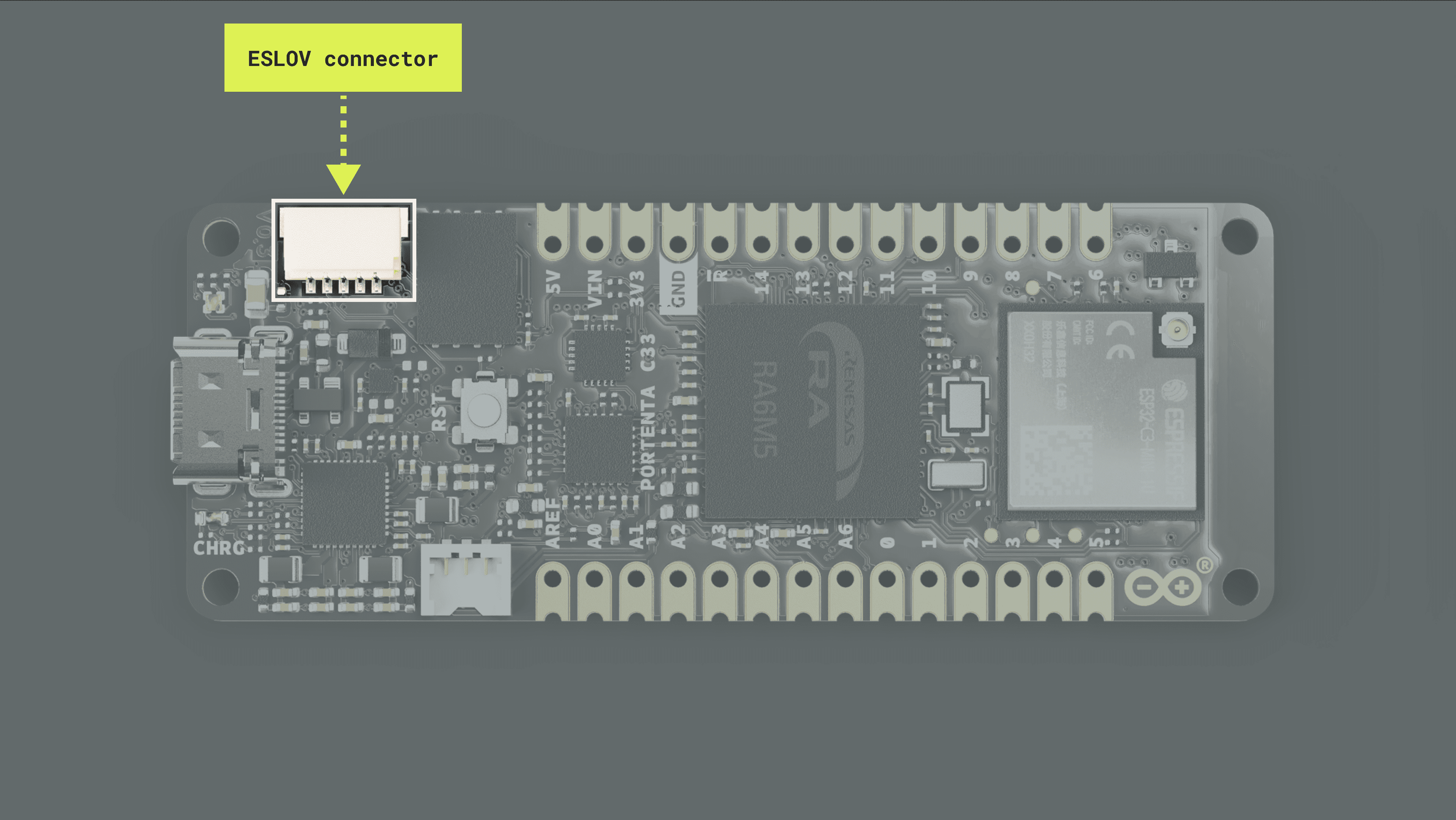
The ESLOV connector is a small 5-pin connector with a 1.00 mm pitch. The mechanical details of the connector can be found in the connector's datasheet.
The pin layout of the ESLOV connector is the following:
- VCC
- INT
- SCL
- SDA
- GND
VCCExternal Memory
The Portenta C33 board features an onboard 16 MB QSPI Flash memory, the MX25L12833F from Macronix®. Having an onboard QSPI Flash memory enhances the capabilities of the Portenta C33, enabling you to develop and run more complex and data-intensive applications.
Some key advantages of having an onboard QSPI Flash memory are the following:
- Storage capacity: The MX25L12833F QSPI Flash memory adds significant non-volatile storage to the board.
- Extended functionality: The additional memory space allows more complex applications to be developed and run on your Portenta C33. This application includes data logging, image processing, audio processing, and executing complex algorithms.
- Firmware updates: The MX25L12833F QSPI Flash memory can also store firmware or software updates for your Arduino board. This means you can update the firmware without requiring a complete reprogramming of the board.
The Arduino Renesas Core has built-in libraries and drivers that immediately let you use the onboard QSPI Flash memory. Let's walk through an example code demonstrating some of the onboard Flash memory capabilities; the main tasks performed in the sketch are initializing the Flash memory, writing to a file, and reading from a file.
1/**2 QSPI Flash File System test3 Name: QSPI_Flash_FileSystem_Test.ino4 Purpose: This sketch test the onboard QSPI Flash memory5 file system by writing and reading a file.6
7 @author Arduino Team8 @version 1.0 20/06/239*/10
11// Include necessary libraries and drivers12#include "QSPIFlashBlockDevice.h"13#include "FATFileSystem.h"14
15// Define constants for file system and test file name16#define QSPI_FS_NAME "qspi"17#define TEST_FILE "test.txt"18
19// Instantiate flash block device and file system20QSPIFlashBlockDevice block_device(PIN_QSPI_CLK, PIN_QSPI_SS, PIN_QSPI_D0, PIN_QSPI_D1, PIN_QSPI_D2, PIN_QSPI_D3); 21FATFileSystem fs(QSPI_FS_NAME);22
23// Define full path to the test file24std::string file_test_name = std::string("/") + std::string(QSPI_FS_NAME) + std::string("/") + std::string(TEST_FILE); 25
26void setup() {27 // Initialize serial communication and wait a connection28 Serial.begin(9600);29 while(!Serial);30
31 // Print test start message32 Serial.println();33 Serial.println("- SIMPLE QSPI FLASH TEST");34 Serial.println();35
36 // Try to mount the QSPI Flash file system37 // If mounting fails, try to format the file system38 int err = fs.mount(&block_device);39 if (err) {40 Serial.println("- No filesystem found, formatting... ");41 err = fs.reformat(&block_device);42 }43 if (err) {44 // If formatting fails, print error and halt45 Serial.println("- Error formatting QSPI Flash ");46 while(1);47 }48
49 // Try to open a test file for writing50 // If file opened successfully, write some text to the file51 FILE* fp = fopen(file_test_name.c_str(), "w");52 if(fp != NULL) {53 Serial.println("- Opened file for writing!");54 char text[] = "Hello from QSPI Flash!\n";55 fwrite(text, sizeof(char), strlen(text), fp);56 // Always close the file after writing to save changes57 fclose(fp);58 }59 else {60 // If file opening fails, print an error message61 Serial.print("- Failed to open file for writing: ");62 Serial.println(file_test_name.c_str());63 }64
65 // Try to open the test file for reading66 // If file opened successfully, read and print its content67 fp = fopen(file_test_name.c_str(), "r");68 if(fp != NULL) {69 Serial.println("- Opened file for reading!");70 char ch;71 while(fread(&ch, sizeof(char), 1, fp) == 1) {72 Serial.print(ch);73 }74 // Always close the file after reading75 fclose(fp);76 }77 else {78 // If file opening fails, print an error message79 Serial.print("Failed to open file for reading: ");80 Serial.println(file_test_name.c_str());81 }82}83
84void loop() {}Here's what each section of the example code does:
- Initialize the onboard Flash memory: After setting up the Serial port, the sketch tries to mount the QSPI Flash file system. If the file system is not found, the code formats the memory to set up a new file system. If there's an error during this process, the code will halt and print an error message to the IDE's Serial Monitor.
- Write to a file: Next, the sketch attempts to open a file named
intest.txt
mode. If this process is successful, it writes the stringwrite
to the file and then closes it. If it cannot open the file, it will print an error message to the IDE's Serial Monitor.Hello from QSPI Flash! - Read from a file: After writing to the file, the sketch attempts to open the same file, but this time in 'read' mode. If successful, it will read the content of the file one character at a time and print each character to the IDE's Serial Monitor. After reading, it closes the file. If it cannot open the file for reading, it will print an error message to the IDE's Serial Monitor.
Secure Element
The Portenta C33 features a secure element onboard, the SE050 from NXP®. A secure element is a component that can store sensitive data and run secure apps; it acts as a vault, protecting what is inside the secure element from attacks. A secure element simplifies the implementation of robust security mechanisms, reducing time to market without requiring specialized security expertise.
The SE050 is a ready-to-use IoT secure element that provides a root of trust at the IC level and gives an IoT system state-of-the-art, edge-to-cloud security capability. It allows for securely storing and provisioning credentials and performing cryptographic operations for security-critical communication and control functions. The Arduino Renesas Core has a built-in library that lets you use the secure onboard element right out of the box, the
SE05XThe Arduino sketch below can help you start with the SE050 and demonstrate its capabilities. The example code generates a new Elliptic Curve (EC) key pair (NIST Curve P-256), signs a SHA256 hash of a predefined input with the private key, and verifies the signature with the public key.
1/**2 SE05X Import and Verify3 Name: import_public_key.ino4 Purpose: This sketch generates a new EC NIST P-256 key pair,5 signs a SHA256 hash of a predefined input with the private key,6 and verifies the signature with the public key.7
8 @author Arduino HW/FW team, modified by Arduino PRO Content Team9 @version 1.0 08/06/2310*/11
12// Include the SE05X library13#include <SE05X.h>14
15// Define IDs for the private and public keys16const int PRIVATE_KEY_ID = 999;17const int PUBLIC_KEY_ID = 899;18
19// Define the input buffer20const byte input[64] = {21 0x00, 0x01, 0x02, 0x03, 0x04, 0x05, 0x06, 0x07, 0x08, 0x09, 0x0a, 0x0b, 0x0c, 0x0d, 0x0e, 0x0f,22 0x10, 0x11, 0x12, 0x13, 0x14, 0x15, 0x16, 0x17, 0x18, 0x19, 0x1a, 0x1b, 0x1c, 0x1d, 0x1e, 0x1f,23 0x20, 0x21, 0x22, 0x23, 0x24, 0x25, 0x26, 0x27, 0x28, 0x29, 0x2a, 0x2b, 0x2c, 0x2d, 0x2e, 0x2f,24 0x30, 0x31, 0x32, 0x33, 0x34, 0x35, 0x36, 0x37, 0x38, 0x39, 0x3a, 0x3b, 0x3c, 0x3d, 0x3e, 0x3f25};26
27/**28 Print a buffer in hexadecimal format.29
30 @param input buffer to print in hexadecimal format.31 @param inputLenght input buffer length.32 @return none.33*/34
35// Function to print a buffer in hexadecimal format36void printBufferHex(const byte input[], size_t inputLength) {37 for (size_t i = 0; i < inputLength; i++) {38 Serial.print(input[i] >> 4, HEX); // Print the high nibble39 Serial.print(input[i] & 0x0f, HEX); // Print the low nibble40 }41 Serial.println();42}43
44void setup() {45 // Initialize serial port with a baud rate of 9600, wait for a connection.46 Serial.begin(9600);47 while (!Serial);48
49 // Initialize the secure element. If the initialization fails, print an error message and halt.50 if (!SE05X.begin()) {51 Serial.println("- Failed to communicate with secure element!");52 while(1);53 }54
55 // Create a buffer for DER-encoded key and define its size.56 byte derBuf[256];57 size_t derSize;58
59 // Generate a new private key with the defined ID.60 SE05X.generatePrivateKey(PRIVATE_KEY_ID, derBuf, sizeof(derBuf), &derSize);61
62 // Print the input buffer on the Serial Monitor.63 Serial.print("- Input is: ");64 printBufferHex(input, sizeof(input));65
66 // Calculate and print the SHA256 hash of the input buffer on the Serial Monitor.67 byte sha256[256];68 size_t sha256Len;69 SE05X.SHA256(input, sizeof(input), sha256, sizeof(sha256), &sha256Len);70 Serial.print("- Input SHA256 is: ");71 printBufferHex(sha256, sha256Len);72
73 // Sign the SHA256 hash with the generated private key.74 byte signature[256];75 size_t signatureLen;76 SE05X.Sign(PRIVATE_KEY_ID, sha256, sha256Len, signature, sizeof(signature), &signatureLen);77
78 // Print the signature on the Serial Monitor.79 Serial.print("Signature using KeyId ");80 Serial.print(PRIVATE_KEY_ID);81 Serial.print(" is: ");82 printBufferHex(signature, signatureLen);83 Serial.println();84
85 // Import the public key to the secure element using the public key ID and the DER-encoded key. 86 SE05X.importPublicKey(PUBLIC_KEY_ID, derBuf, derSize);87
88 // To make the signature verification fail, uncomment the next line:89 // signature[0] = 0x00;90
91 // Verify the signature. If the verification fails, print an error message on the Serial Monitor. 92 if (SE05X.Verify(PUBLIC_KEY_ID, sha256, sha256Len, signature, signatureLen)) {93 Serial.println("Verified signature successfully :D");94 } else {95 Serial.println("- Failed to verify signature!");96 }97}98
99// Loop function100void loop() {101 // This function remains empty, as no repetitive task needs to be done in this example.102}Here's what each section of the example code does:
- Input buffer initialization: The sketch begins by initializing a 64-byte input buffer.
- Buffer print function: A function named
is defined to print the contents of a buffer in hexadecimal format to the IDE's Serial Monitor.printBufferHex() - Secure element initialization: In the
function, communication with the secure element is initiated. If it fails, an error message is shown in the IDE's Serial Monitor, and the program is halted.setup() - Private key generation: The secure element generates an Elliptic Curve (EC) NIST P-256 private key. The key ID is set to 999, and the generated key is returned in DER format.
- Input hash and signature: The SHA256 hash of the input buffer is computed and printed, then signed using the generated private key.
- Public key import: The public key derived from the generated private key is imported to the secure element with key ID 899.
- Signature verification: The example code then verifies the signature using the imported public key and prints a success or failure message accordingly.
Arduino Cloud
The Portenta C33 is fully compatible with the Arduino Cloud IoT, which simplifies how professional applications are developed and tracked. By using the IoT Cloud, you can, for example, monitor sensor data, control your board and actuators connected to it remotely, and update your device's firmware over-the-air.
In case it is the first time you are using the Arduino Cloud:
- To use the Arduino Cloud, you need an account. If you do not have an account, create one for free here.
- To use the Arduino Web Editor or Arduino Cloud, the Arduino Create Agent must be running on your computer. You can install the Arduino Create Agent here.
Let's walk through a step-by-step demonstration of how to use your Portenta C33 board with the Arduino Cloud.
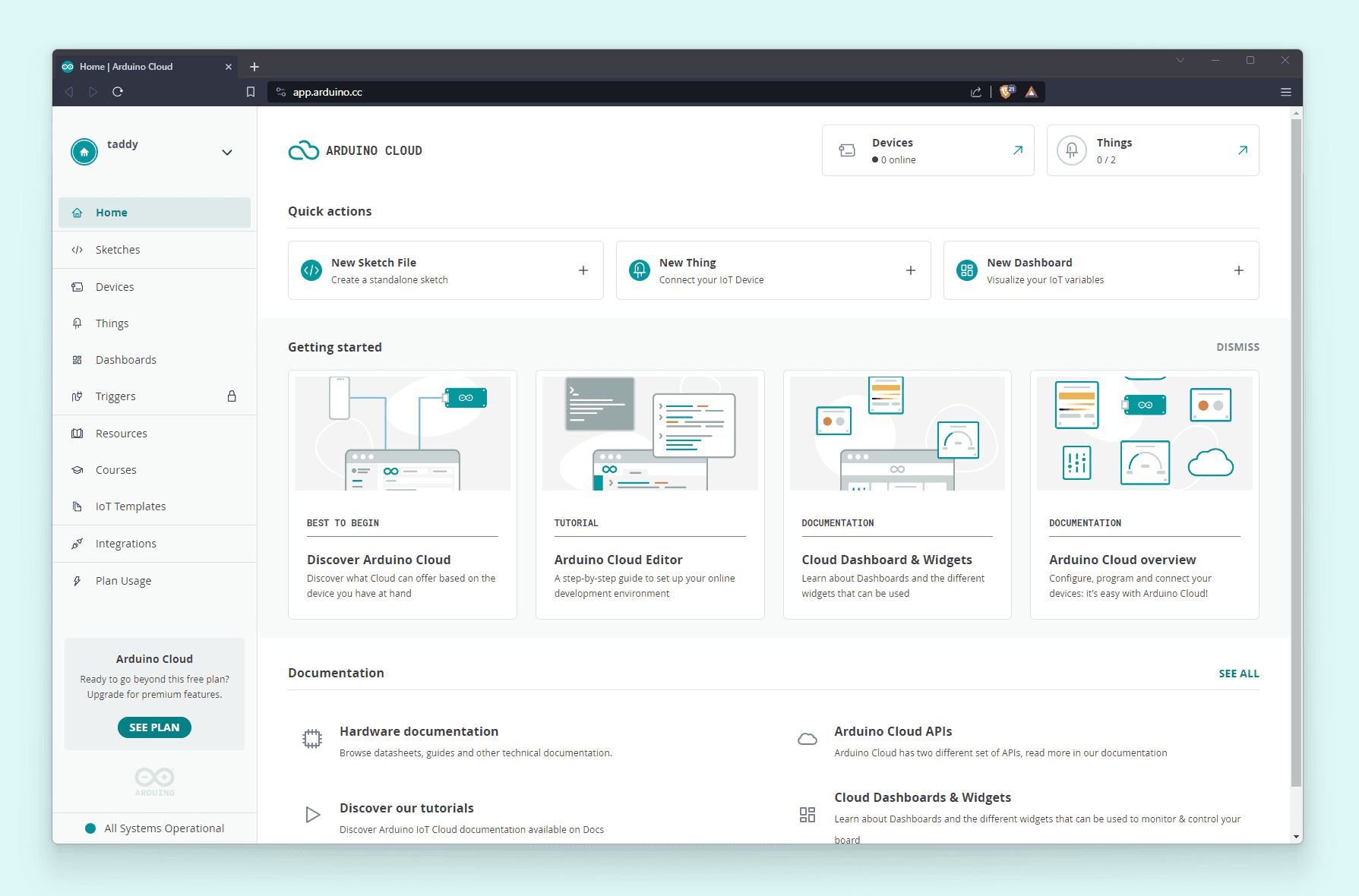
Log in to your Arduino Cloud account; you should see the following:
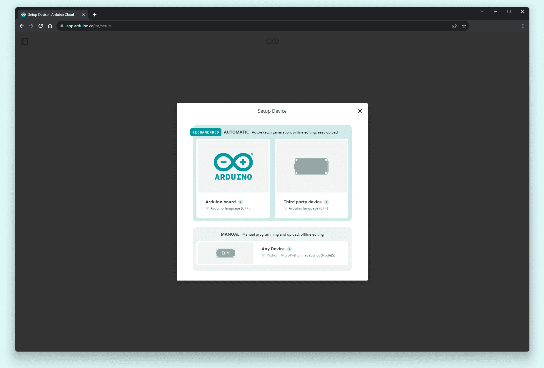
First, provision your Portenta C33 board on your Arduino Cloud space. To do this, navigate to Devices and then click on the ADD DEVICE button:

The Setup Device pop-up window will appear. Navigate into AUTOMATIC and select the Arduino board option:
After a while, your Portenta C33 board should be discovered by the Arduino Cloud, as shown below:
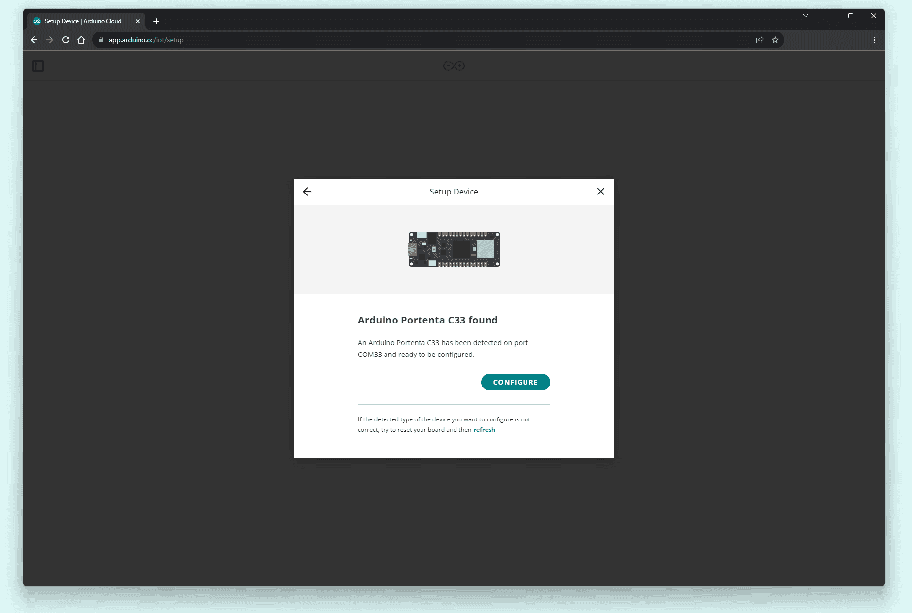
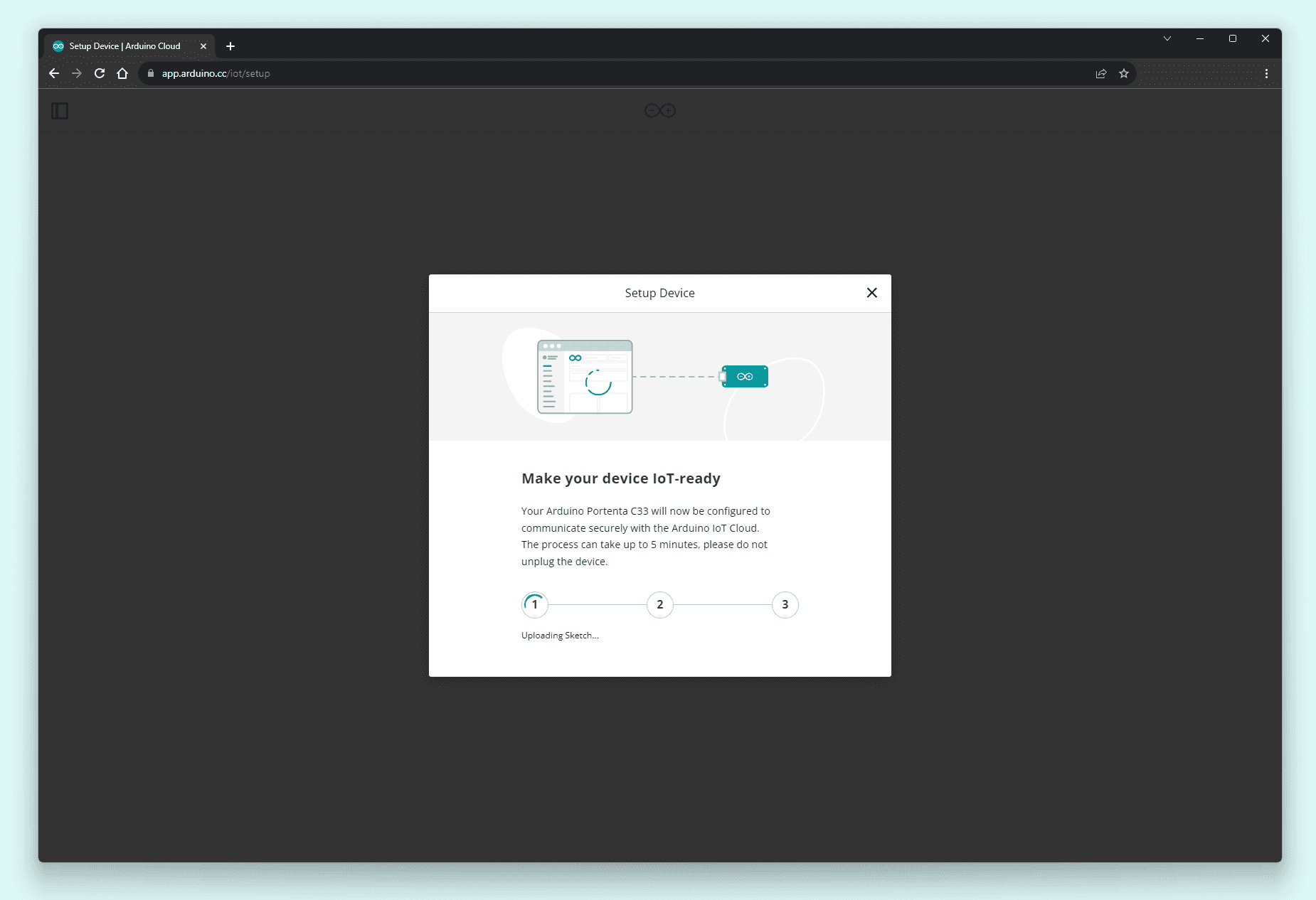
Click the CONFIGURE button, give your board a name, and select the type of network connection. In this example, we will use a Wi-Fi® connection; you can also use an Ethernet connection with a Portenta Max Carrier, a Portenta Breakout, a Portenta Vision Shield or a custom-made board with an Ethernet connector. Your Portenta C33 board will be configured to securely communicate with the Arduino Cloud. This process can take a while.
Once the Portenta C33 has been configured, let's create a "Thing" to test the connection between your board and the Arduino Cloud. Navigate into Things and select the CREATE THING button; give your thing a name.
Navigate into Associate Device and click the Select Device button. Select your Portenta C33 board and associate it with your "Thing." Then, navigate into Network and click the Configure button; enter your network credentials.
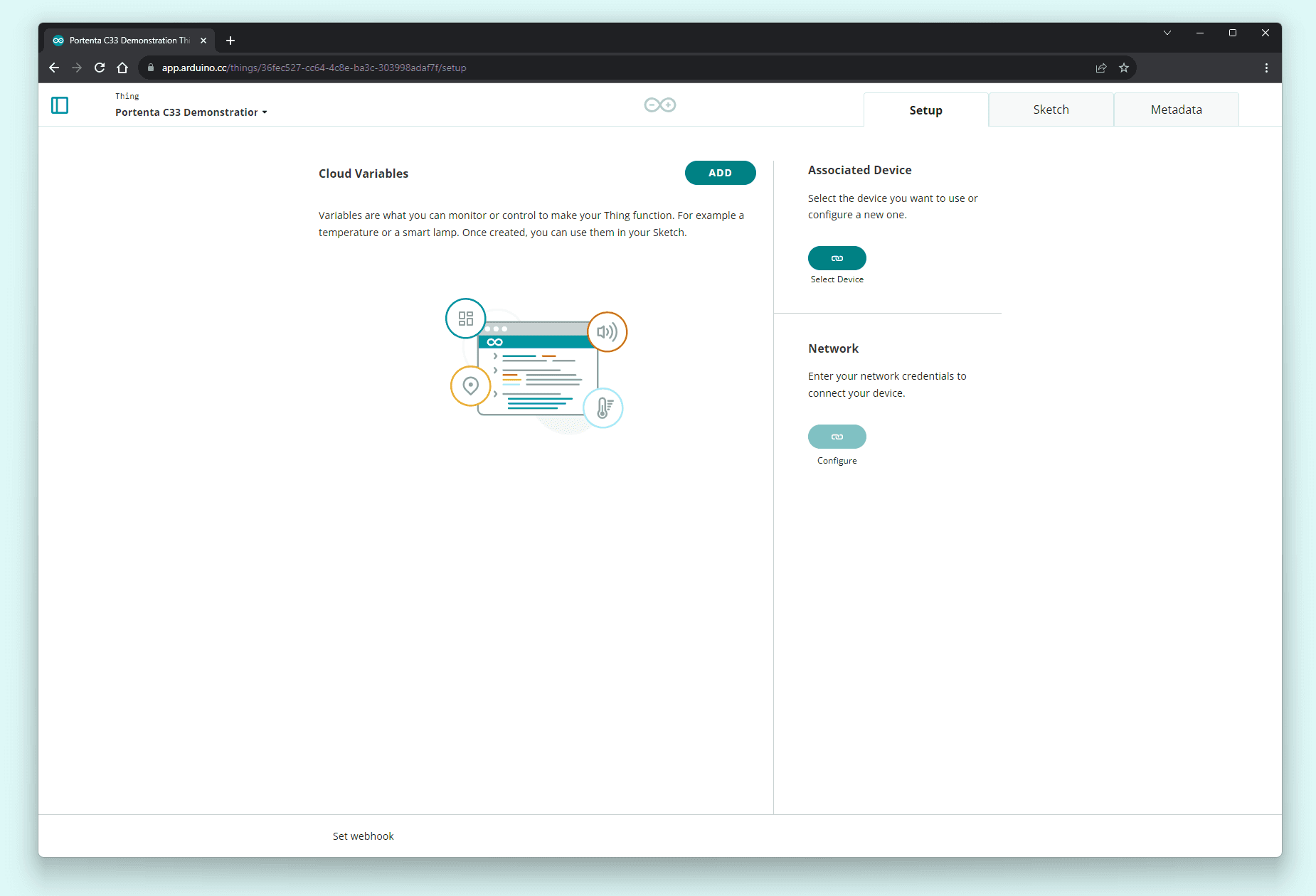
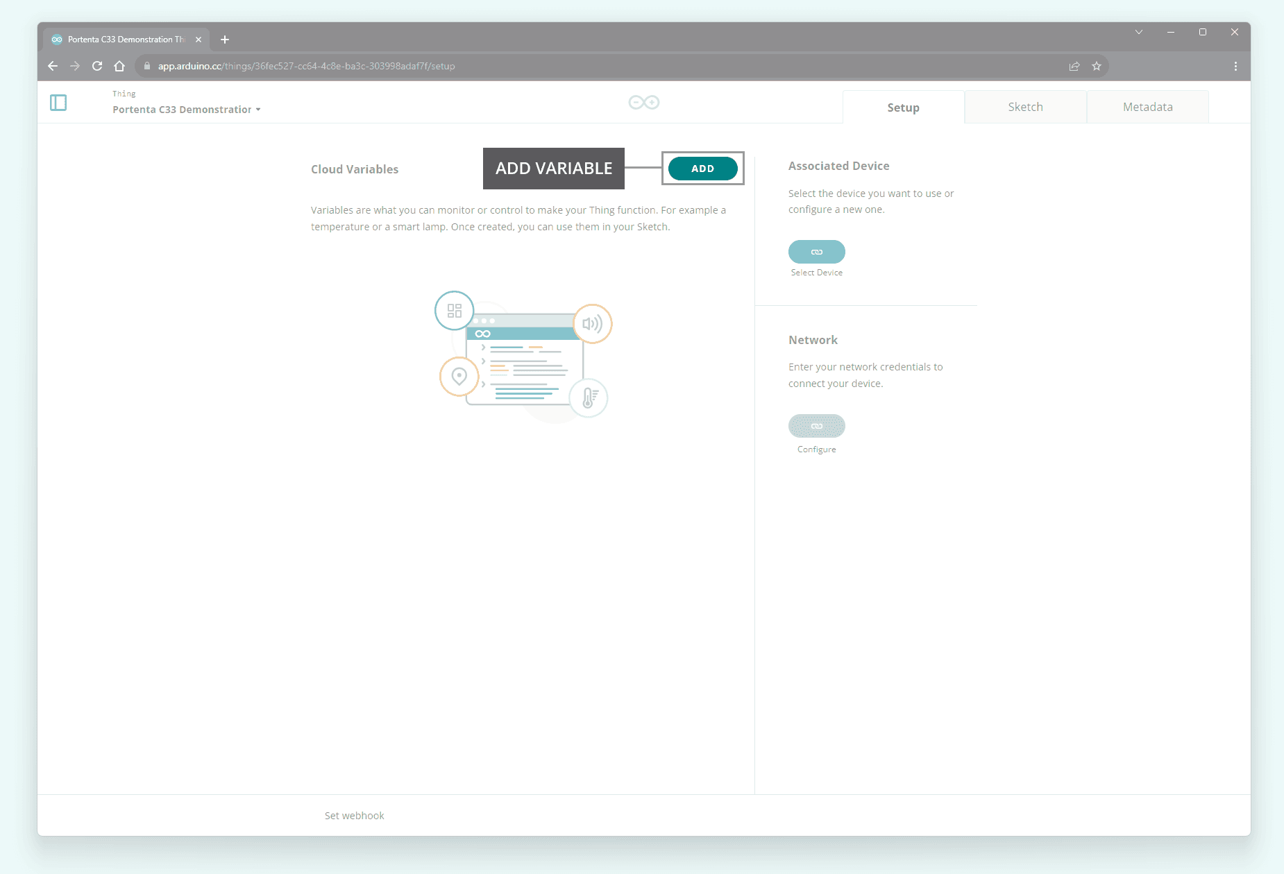
The project is now ready to add some variables to your "Thing"; navigate into Cloud Variables and click the ADD button to add variable.
Add one variable with the following characteristics:
- Name:
led - Variable type:
Boolean - Variable permission
Read & Write - Variable update policy:
On change
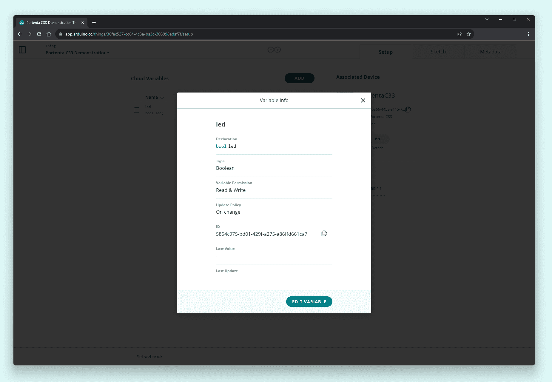
You should see the
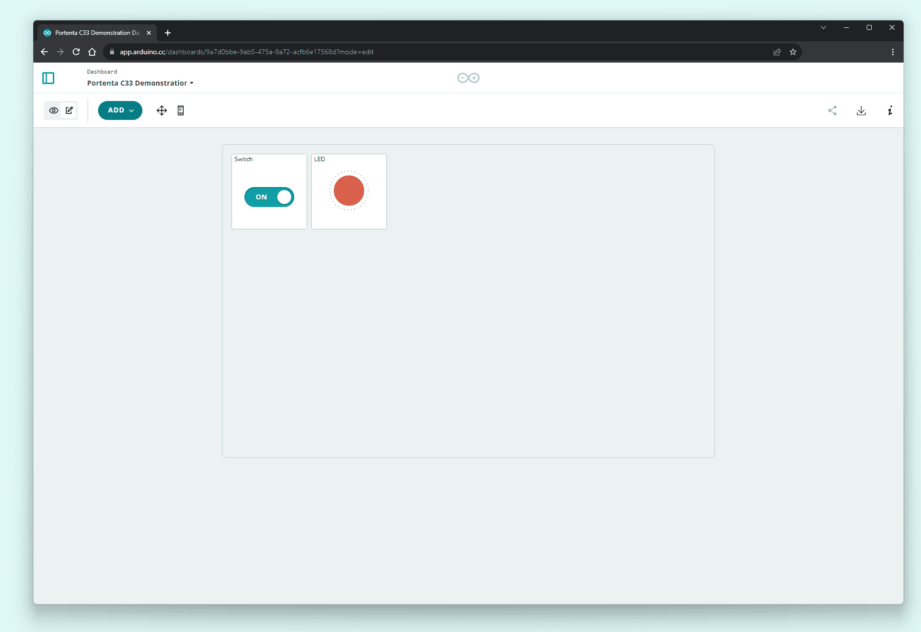
ledAdd the following widgets to your dashboard:
- Switch: name the widget
and link it to theSwitch
variable you created before.led - LED: name the widget
and link it to theled
variable you created before.led
Your dashboard should look like the following:
Go back to your Things and open the "Thing" you created. In the "Thing" setup page, navigate into Sketch, where you should see the online editor.
In the generated sketch, define
LED_BUILTINsetup()1void setup() {2 // Initialize serial and wait for port to open:3 Serial.begin(9600);4 // This delay gives the chance to wait for a Serial Monitor without blocking if none is found5 delay(1500);6
7 // LED_BUILTIN macro access the onboard green LED8 pinMode(LED_BUILTIN, OUTPUT);9
10 // Defined in thingProperties.h11 initProperties();12
13 // Connect to Arduino Cloud14 ArduinoCloud.begin(ArduinoIoTPreferredConnection);15
16 /*17 The following function allows you to obtain more information18 related to the state of network and IoT Cloud connection and errors19 the higher number the more granular information you’ll get.20 The default is 0 (only errors).21 Maximum is 422 */23 setDebugMessageLevel(2);24 ArduinoCloud.printDebugInfo();25}In the
onLedChange()ledled1/*2 Since Led is READ_WRITE variable, onLedChange() is3 executed every time a new value is received from IoT Cloud.4*/5void onLedChange() {6 digitalWrite(LED_BUILTIN, !led);7}The complete example code can be found below:
1/*2 Sketch generated by the Arduino Cloud3
4 Arduino Cloud Variables description5
6 The following variables are automatically generated and updated when changes are made to the Thing7
8 bool led;9
10 Variables which are marked as READ/WRITE in the Cloud Thing will also have functions11 which are called when their values are changed from the Dashboard.12 These functions are generated with the Thing and added at the end of this sketch.13*/14
15#include "thingProperties.h"16
17void setup() {18 // Initialize serial and wait for port to open:19 Serial.begin(9600);20 // This delay gives the chance to wait for a Serial Monitor without blocking if none is found21 delay(1500);22
23 // Defined in thingProperties.h24 initProperties();25
26 // Connect to Arduino Cloud27 ArduinoCloud.begin(ArduinoIoTPreferredConnection);28
29 /*30 The following function allows you to obtain more information31 related to the state of network and IoT Cloud connection and errors32 the higher number the more granular information you’ll get.33 The default is 0 (only errors).34 Maximum is 435 */36 setDebugMessageLevel(2);37 ArduinoCloud.printDebugInfo();38}39
40void loop() {41 ArduinoCloud.update();42 // Your code here43}44
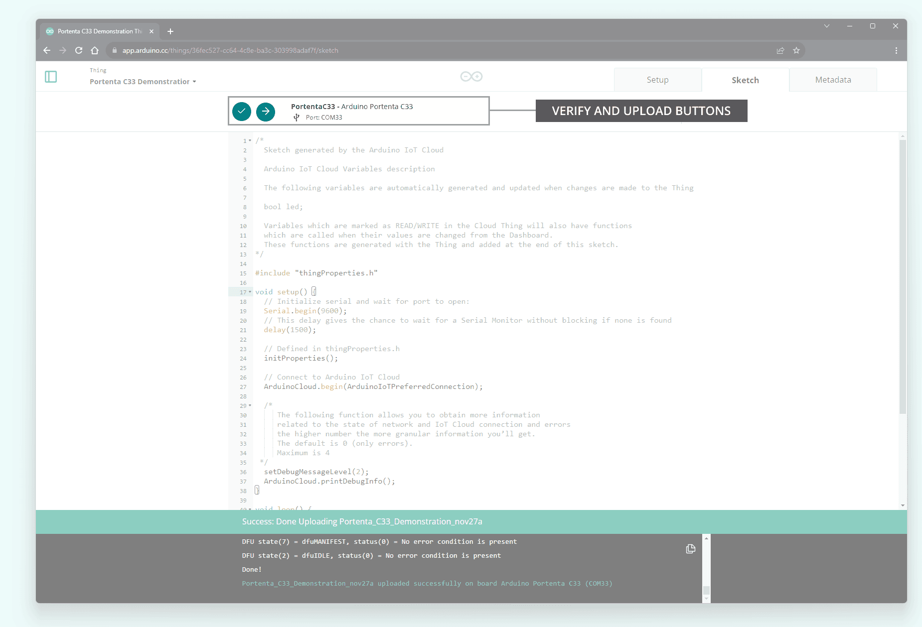
45/*46 Since Led is READ_WRITE variable, onLedChange() is47 executed every time a new value is received from IoT Cloud.48*/49void onLedChange() {50 digitalWrite(LED_BUILTIN, !led);51}To upload the code to the Portenta C33 from the online editor, click the green Verify button to compile the sketch and check for errors, then click the green Upload button to program the board with the sketch.
Navigate into Dashboards again, your board should connect to the Wi-Fi® network you defined before (you can follow the connection process with the online editor integrated Serial Monitor). Your board's green LED should light on or off when the position of the switch changes.
Support
If you encounter any issues or have questions while working with the Portenta C33, we provide various support resources to help you find answers and solutions.
Help Center
Explore our Help Center, which offers a comprehensive collection of articles and guides for the Portenta C33. The Arduino Help Center is designed to provide in-depth technical assistance and help you make the most of your device.
Forum
Join our community forum to connect with other Portenta C33 users, share your experiences, and ask questions. The forum is an excellent place to learn from others, discuss issues, and discover new ideas and projects related to the Portenta C33.
Contact Us
Please get in touch with our support team if you need personalized assistance or have questions not covered by the help and support resources described before. We're happy to help you with any issues or inquiries about the Portenta C33.
Suggest changes
The content on docs.arduino.cc is facilitated through a public GitHub repository. If you see anything wrong, you can edit this page here.
License
The Arduino documentation is licensed under the Creative Commons Attribution-Share Alike 4.0 license.