LoRa® LED Control with MKR WAN 1300
Learn how to connect two boards using LoRa®, and how to control an LED remotely from another board.
In this tutorial, we will set up two Arduino MKR WAN 1300 to host a remote LED control. One board will be set up as a sender with a pushbutton that when it is pressed, an LED on the other board will turn on or off.
We will use the LoRa library for the communication, and we will not use any external service.
Hardware & Software Needed
- Arduino IDE (online or offline).
- LoRa library installed, see the github repository.
- 2x Arduino MKR WAN 1300.
- 2x Antenna.
- 1x Pushbutton.
- 1x Generic LED.
- Jumper wires.
- Breadboard(s).
- 2x Micro USB cable.
Circuit
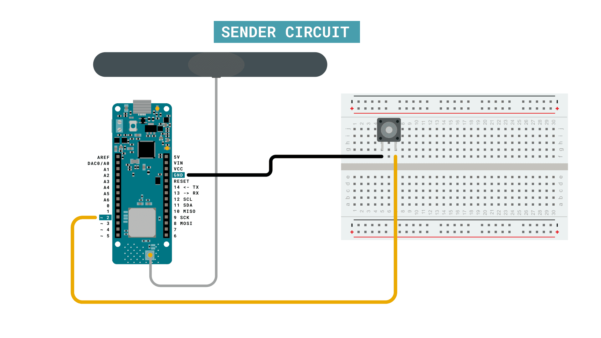
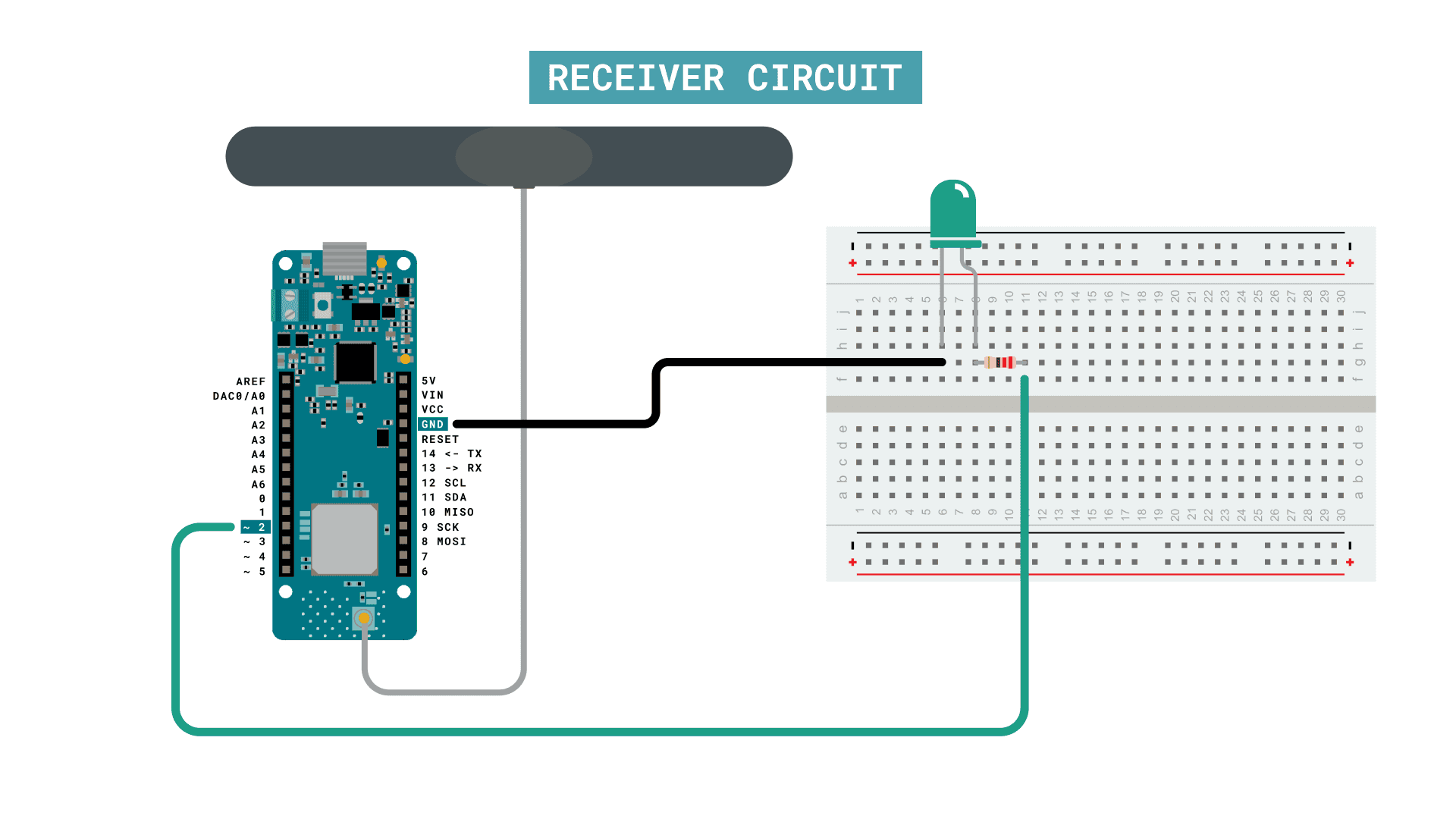
Follow the wiring diagrams below to create the circuits for the sender and receiver boards.
Sender Circuit
Receiver Circuit
Let's Start
In this tutorial, we will achieve a basic trigger over the LoRa® network. When we press a button on one of the MKR WAN 1300 boards, an LED will light up on another. This is quite a simple setup, but it can be useful for long range, low power communication!
But let's take a look at what we need to include in the code. As we are using two different boards, we will also need to create two separate sketches.
To create the sender sketch, we will have to do the following steps:
- Initialize the SPI and LoRa libraries.
- Create a counter variable.
- Set the radio frequency to 868E6 (Europe) or 915E6 (North America).
- Create an if statement that checks if the button is pressed.
- If button is pressed, begin a packet, and print the text "button pressed".
- End packet.
- Increase counter each loop and print it in Serial Monitor.
To create the receiver sketch, we will have to do the following steps:
- Initialize the SPI and LoRa libraries.
- Create a string with the message "button pressed" stored.
- Set the radio frequency to 868E6 (Europe) or 915E6 (North America).
- Create a function to parse incoming packet.
- Check if incoming string matches string we have created.
- Each time string matches, switch a boolean.
- Use boolean as a trigger to turn an LED on or off.
Creating the Program
1. First, let's make sure we have the drivers installed. If we are using the Web Editor, we do not need to install anything. If we are using an offline editor, we need to install it manually. This can be done by navigating to Tools > Board > Board Manager.... Here we need to look for the Arduino SAMD boards (32-bits Arm® Cortex®-M0+) and install it.
2. Now we need to download the LoRa library from this repository, where you can install it by navigating to Sketch > Include Library > Add .ZIP Library... in the offline IDE.
Programming the Sender
In the initialization we will include the SPI and LoRa libraries. We will then create the
counterbuttonbuttonState1#include <SPI.h>2#include <LoRa.h>3
4int counter = 0;5int button = 2;6int buttonState;In the
setup()buttonINPUT_PULLUPwhile(!Serial);We will then initialize the LoRa library, where we will set the radio frequency to 868E6, which is used in Europe for LoRa® communication. If we are located in North America, we need to change this to 915E6.
1void setup() {2 pinMode(button, INPUT_PULLUP);3
4 Serial.begin(9600);5
6 while (!Serial);7 Serial.println("LoRa Sender");8
9 if (!LoRa.begin(868E6)) {10 Serial.println("Starting LoRa failed!");11 while (1);12 }13
14 delay(1000);15}In the
loop()buttonStateIf the button is pressed, we begin a packet by using the command,
LoRa.beginPacket()LoRa.print()LoRa.endPacket()1void loop() {2 buttonState = digitalRead(button);3
4 if (buttonState == LOW) {5 // send packet6 LoRa.beginPacket();7 LoRa.print("button pressed");8 LoRa.endPacket();9 counter++;10 Serial.print("Sending packet: ");11 Serial.println(counter);12 delay(500);13 }14}Programming the Receiver
In the initialization we will first include the SPI and LoRa libraries. Then we will create two strings: one empty, and one with the message "button pressed" stored. The
contentsbuttonPressWe then create the boolean
xbuttonPresscontentsled1#include <SPI.h>2#include <LoRa.h>3
4String contents = "";5String buttonPress = "button pressed";6bool x;7
8int led = 2;In the
setup()ledwhile(!Serial);We will then initialize the LoRa library, where we will set the radio frequency to 868E6, which is used in Europe for LoRa® communication. If we are located in North America, we need to change this to 915E6.
1void setup() {2
3 pinMode(led, OUTPUT);4 Serial.begin(9600);5 while (!Serial);6 //Wire.begin();7 Serial.println("LoRa Receiver");8
9 if (!LoRa.begin(868E6)) {10 Serial.println("Starting LoRa failed!");11 while (1);12 }13}Inside the
loop()int packetSize = LoRa.parsePacket();contentsWe then compare the
contentsbuttonPressxx = !x;xtruefalseFinally, after the action has happened, we reset the
contents1void loop() {2 // try to parse packet3 int packetSize = LoRa.parsePacket();4 if (packetSize) {5 // received a packet6 Serial.print("Received packet '");7
8 // read packet9 while (LoRa.available()) { 10 contents += (char)LoRa.read();11 }12 13 // print RSSI of packet14 Serial.print("' with RSSI ");15 Serial.println(LoRa.packetRssi());16 Serial.println(contents);17
18 if(contents.equals(buttonPress)){19 x = !x;20 }21
22 if(x == true) {23 digitalWrite(led, HIGH);24 Serial.println("led on");25 }26 else {27 digitalWrite(led, LOW);28 Serial.println("led off");29 }30 31 contents = "";32 }33}Complete Code
If you choose to skip the code building section, the complete code can be found below:
Sender Code
1#include <SPI.h>2#include <LoRa.h>3
4int counter = 0;5int button = 2;6int buttonState;7
8void setup() {9 pinMode(button, INPUT_PULLUP);10 11 Serial.begin(9600);12 13 while (!Serial);14 Serial.println("LoRa Sender");15 16 if (!LoRa.begin(868E6)) {17 Serial.println("Starting LoRa failed!");18 while (1);19 }20 delay(1000);21}22
23void loop() {24 buttonState = digitalRead(button);25 26 if (buttonState == LOW) {27 // send packet28 LoRa.beginPacket();29 LoRa.print("button pressed");30 LoRa.endPacket();31 counter++;32 Serial.print("Sending packet: ");33 Serial.println(counter);34 delay(500);35 }36}Receiver Code
1#include <SPI.h>2#include <LoRa.h>3
4String contents = "";5String buttonPress = "button pressed";6bool x;7
8int led = 2;9
10void setup() {11
12 pinMode(led, OUTPUT);13 Serial.begin(9600);14 while (!Serial);15 //Wire.begin();16 Serial.println("LoRa Receiver");17
18 if (!LoRa.begin(868E6)) {19 Serial.println("Starting LoRa failed!");20 while (1);21 }22}23
24void loop() {25 // try to parse packet26 int packetSize = LoRa.parsePacket();27 if (packetSize) {28 // received a packet29 Serial.print("Received packet '");30
31 // read packet32 while (LoRa.available()) { 33 contents += (char)LoRa.read();34 }35 36 // print RSSI of packet37 Serial.print("' with RSSI ");38 Serial.println(LoRa.packetRssi());39 Serial.println(contents);40
41 if(contents.equals(buttonPress)){42 x = !x;43 }44
45 if(x == true) {46 digitalWrite(led, HIGH);47 Serial.println("led on");48 }49 else {50 digitalWrite(led, LOW);51 Serial.println("led off");52 }53 54 contents = "";55 }56}Upload Sketch and Testing the Program
Once we are finished with the coding, we can upload the sketches to each board. The easiest way to go forward is to have two separate computers, as we will need to have the Serial Monitor open for both boards. Alternatively, we can use a Serial interfacing program called Putty. But for demonstration purposes, it is good to use two computers. This way, you can move the boards further away from each other while testing the signal.
Sending Package
After we have uploaded the code to the sender, we need to open the Serial Monitor to initialize the program. If everything is working, it will start listening for button presses. If the button is pressed, it will print the message
"Sending packet: x" x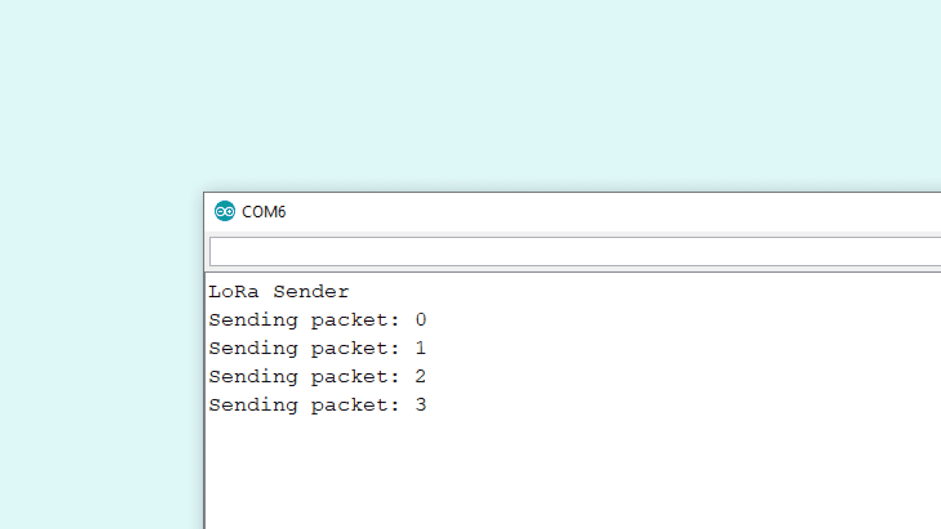
Receiving Package
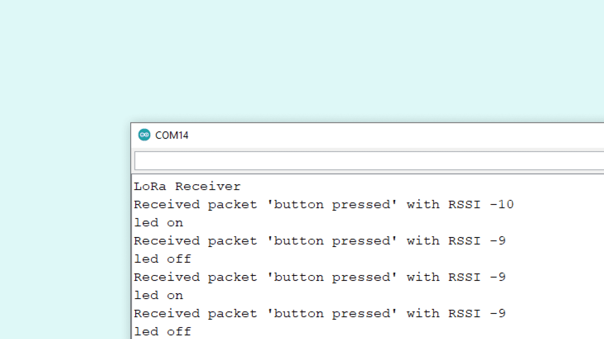
After we have uploaded the code to the receiver, we need to open the Serial Monitor to initialize the program. If everything works, we should now pick up any package we send from the other device. The package we receive should contain the message "button pressed", followed by RSSI (Received Signal Strength Indication). The closer this value is to 0, the stronger the signal are. After we receive the value, the LED will turn on or off, and print its state in the Serial Monitor.
Experimenting with This Setup
Now that we have communication between the boards, we can do a simple test with the signal. If we move the sender device away from the receiver device, we will start noticing changes in the RSSI. For example, while conducting this test, the sender device was moved around 20 meters away from the receiver, which decreased the RSSI to about -60.
Troubleshoot
If the code is not working, there are some common issues we might need to troubleshoot:
- Antenna is not connected properly.
- The radio frequency is wrong. Remember, 868E6 for Europe and 915E6 for Australia & North America.
- We have not opened the Serial Monitor.
- We are using the same computer for both boards without a serial interfacing program.
Conclusion
This tutorial demonstrates a simple, yet powerful communication setup, featuring two MKR WAN 1300 boards and how to remotely control an LED using LoRa®.
Suggest changes
The content on docs.arduino.cc is facilitated through a public GitHub repository. If you see anything wrong, you can edit this page here.
License
The Arduino documentation is licensed under the Creative Commons Attribution-Share Alike 4.0 license.