Getting Started with the Arduino TFT Screen
The first steps to setting up the Arduino TFT Screen
This is a retired product.
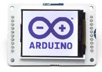
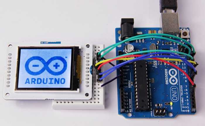
The Arduino TFT screen is a backlit TFT LCD screen with a micro SD card slot in the back. You can draw text, images, and shapes to the screen with the TFT library.
The screen's pin layout is designed to easily fit into the socket of an Arduino Esplora and Arduino Robot, but it can be used with any Arduino board.
The TFT library is included with Arduino IDE 1.0.5 or later.
Library
The Arduino TFT library extends the Adafruit GFX, and Adafruit ST7735 libraries that it is based on. The GFX library is responsible for the drawing routines, while the ST7735 library is specific to the screen on the Arduino screen. The Arduino specific additions were designed to work as similarly to the Processing API as possible.
The library is backwards compatible, which means you can still use the Adafruit functions described here.
The TFT library relies on the SPI library, which must be included in any sketch that uses the scree. If you wish to use the SD card, you need to include the SD library as well.
Screen layout
By default, the screen is oriented so it is wider than it is tall. The top of the screen is the same side as the text 'SD CARD''. In this orientation, the screen is 160 pixels wide and 128 pixels high.
When thinking about coordinates on the screen, imagine a grid. Each square in the grid is a pixel. You can identify the placement of pixels with specific coordinates. A dot in the top left corner would have coordinates of 0,0. If this dot were to move to the top right of the screen, its coordinates would be 0, 159; in the bottom left corner, the coordinates would be 127,0, and in the bottom right it would be 127,159.
It is possible to use the screen in a vertical, (also called "portrait") orientation, by calling
setRotation(0)screen.width()screen.height()Colors
The screen has the ability to show 16-bit color. The red and blue have 5-bits of resolution each (32 levels of red and blue), the green has 6-bits of resolution (64 different levels). For consistency with other applications, the library deals with color in 8-bit values for the red, green, and blue channels (0-255), and scales the colors appropriately.
Hardware vs software SPI interface
The screen can be configured for use in two ways. One is to use an Arduino's hardware SPI interface. The other is to declare all the pins manually. There is no difference in the functionality of the screen between the two methods, but using hardware SPI is significantly faster when drawing.
If you plan on using the SD card on the TFT module, you must use hardware SPI.
All the examples are written for hardware SPI use.
Connecting the screen
Connecting to the Esplora
There is a socket on the front of the Esplora for the screen. Insert the screen into the socket with the blue tab that says "SD Card" closest to the USB port.

Connecting to other Arduino boards
To connect the screen to other Arduino boards, read the tutorial on this link.
Write your first program
To get started with the screen, first write a program that will draw a line, then 2 rectangles horizontally across the screen in different colors.
The first set of instructions are for the Uno, Leonardo, and similar boards. For use with the Esplora, see below.
First, declare the pins to use, import the necessary libraries, and instantiate a named instance of the TFT library. :
1#include <TFT.h> // Hardware-specific library2#include <SPI.h>3
4#define CS 105#define DC 96#define RESET 87
8// pin definition for the Leonardo9// #define CS 710// #define DC 011// #define RESET 112
13TFT myScreen = TFT(CS, DC, RESET);In
setup()begin()background()1void setup(){2
3 myScreen.begin();4
5 myScreen.background(0,0,0); // clear the screen with black6
7 delay(1000); // pause for dramatic effect8}in
loop()line()line()rect()rect()stroke()fill()stroke()fill()noStroke()stroke()noStroke()1void loop(){2
3 myScreen.stroke(255, 0, 0); // set the stroke color to red4
5 myScreen.line(0, 10, myScreen.width(), 10); // draw a line across the screen6
7 delay(1000);8
9 myScreen.noStroke(); // don't draw a line around the next rectangle10
11 myScreen.fill(0,255,0); // set the fill color to green12
13 myScreen.rect(0,20,myScreen.width(),10); //draw a rectangle across the screen14
15 delay(1000);16
17 myScreen.fill(0,0,255); // set the fill color to blue18
19 myScreen.stroke(255,255,255); // outline the rectangle with a white line20
21 myScreen.rect(0,45,myScreen.width(),45); // draw a fat rectangle22
23 delay(1000);24
25 myScreen.background(0,0,0); // clear the screen before starting again26
27 delay(1000);28}If you are using an Esplora, the structure of the program is the exact same. As the Esplora has a socket designed for the screen, and the pins for using the screen are fixed, an Esplora only object is created when targeting sketches for that board. You can reference the screen attached to an Esplora through
EsploraTFTYou do not need to declare any pins in your sketch; the object is instantiated for you automatically :
1#include <TFT.h> // Hardware-specific library2#include <SPI.h>3#include <Esplora.h>4
5void setup(){6
7 EsploraTFT.begin();8
9 EsploraTFT.background(0,0,0); // clear the screen with black10
11 delay(1000); // pause for dramatic effect12}13
14void loop(){15
16 EsploraTFT.stroke(255, 0, 0); // set the stroke color to red17
18 EsploraTFT.line(0, 10, EsploraLCD.width(), 10); // draw a line across the screen19
20 delay(1000);21
22 EsploraTFT.noStroke(); // don't draw a line around the next rectangle23
24 EsploraTFT.fill(0,255,0); // set the fill color to green25
26 EsploraTFT.rect(0,20,EsploraTFT.width(),20); //draw a rectangle across the screen27
28 delay(1000);29
30 EsploraTFT.fill(0,0,255); // set the fill color to blue31
32 EsploraTFT.stroke(255,255,255); // outline the rectangle with a white line33
34 EsploraTFT.rect(0,45,EsploraTFT.width(),50); // draw a fat rectangle35
36 delay(1000);37
38 EsploraTFT.background(0,0,0); // clear the screen before starting again39
40 delay(1000);41}Movement across the screen
To give the illusion of motion, you need to quickly erase and draw images on the screen. When using Processing on a powerful computer, you can call
background()draw()background()To create the illusion of motion, it's usually best to check if an object has moved each time through
loop()This example draws a single point, and has it bounce around on the screen. You'll set up the program in the same way you did previously, adding some variables to keep track of the point's current and previous locations, as well as the velocity and direction of the point.
1#include <TFT.h> // Hardware-specific library2#include <SPI.h>3
4#define CS 105#define DC 96#define RESET 87
8// pin definition for the Leonardo9// #define CS 710// #define DC 011// #define RESET 112
13TFT myScreen = TFT(CS, DC, RESET);14
15// initial position of the point is the middle of the screen16// initial position of the point is the middle of the screen17int xPos = 80;18int yPos = 64;19
20// direction and speed21int xDir = 1;22int yDir = 1;23
24// variables to keep track of the point's location25int xPrev = xPos;26int yPrev = yPos;27
28void setup(){29
30 myScreen.begin();31
32 myScreen.background(0,0,0); // clear the screen33}In @@loop()@ you'll first update the position of the dot by adding the direction to the x and y position variables. After that, check to see if there is a difference between the current and the previous locations of the point. If there is a difference, erase the previous location by filling in the dot the same color as the background, then drawing a new dot in the updated location. If the point happens to run into the boundaries of the screen, have it reverse direction.
1void loop(){2
3 // update the location of the dot4
5 xPos = xPos + xDir;6
7 yPos = yPos + yDir;8
9 // check if the current location is different than the previous10
11 if(xPos != xPrev || yPos != yPrev){12
13 myScreen.stroke(0,0,0); // set the stroke color to black14
15 myScreen.point(xPrev, yPrev); // color in the previous point16
17 }18
19 // draw a point in the current location20
21 myScreen.stroke(255,255,255);22
23 myScreen.point(xPos, yPos);24
25 // if the x or x position is at the screen edges, reverse direction26
27 if(xPos >= 160 || xPos <= 0){28
29 xDir = xDir*-1;30
31 }32
33 if(yPos >= 128 || yPos <= 0){34
35 yDir = yDir*-1;36
37 }38
39 // update the point's previous location40
41 xPrev=xPos;42
43 yPrev=yPos;44
45 // a 33ms delay means the screen updates 30 times a second46
47 delay(33);48
49}The Esplora version is below :
1#include <TFT.h> // Hardware-specific library2#include <SPI.h>3#include <Esplora.h>4
5// initial position of the point is the middle of the screen6int xPos = 80;7int yPos = 64;8
9// direction and speed10int xDir = 1;11int yDir = 1;12
13// variables to keep track of the point's location14int xPrev, yPrev;15
16void setup(){17
18 EsploraTFT.begin();19
20 EsploraTFT.background(0,0,0);21}22
23void loop(){24
25 // update the location of the dot26
27 xPos = xPos + xDir;28
29 yPos = yPos + yDir;30
31 // check if the current location is different than the previous32
33 if(xPos != xPrev || yPos != yPrev){34
35 EsploraTFT.stroke(0,0,0); // set the stroke color to black36
37 EsploraTFT.point(xPrev, yPrev); // color in the previous point38
39 }40
41 // draw a point in the current location42
43 EsploraTFT.stroke(255,255,255);44
45 EsploraTFT.point(xPos, yPos);46
47 // if the x or x position is at the screen edges, reverse direction48
49 if(xPos >= 160 || xPos <= 0){50
51 xDir = xDir*-1;52
53 }54
55 if(yPos >= 128 || yPos <= 0){56
57 yDir = yDir*-1;58
59 }60
61 // update the point's previous location62
63 xPrev=xPos;64
65 yPrev=yPos;66
67 // slight pause68
69 delay(33);70
71}Draw some text
The TFT library includes a basic font for drawing text on screen. By default, characters are 5 pixels wide and 8 pixels tall. It is possible to change the font size to 10x16, 15x24, or 20x32. For additional information on the underlying font capabilities, see the Adafruit page on graphic primitives.
In this example, you'll create a basic counter that will update a number on screen every half second. As in the earlier examples, include the necessary libraries and variables before
setup()In
setup()setTextSize()1#include <TFT.h> // Hardware-specific library2#include <SPI.h>3
4#define CS 105#define DC 96#define RESET 87
8// pin definition for the Leonardo9// #define CS 710// #define DC 011// #define RESET 112
13TFT myScreen = TFT(CS, DC, RESET);14
15// variable to keep track of the elapsed time16int counter = 0;17// char array to print time18char printout[4];19
20void setup(){21
22 myScreen.begin();23
24 myScreen.background(0,0,0); // clear the screen25
26 myScreen.stroke(255,0,255);27
28 // static text29
30 myScreen.text("Running for",0,0);31
32 myScreen.text("seconds",0,30);33
34 // increase font size for text in loop()35
36 myScreen.setTextSize(3);37}In
loop()1void loop(){2
3 // get elapsed time4
5 counter = millis();6
7 // convert to a string8
9 String elapsedTime = String(counter/1000);10
11 // add to an array12
13 elapsedTime.toCharArray(printout,4);14
15 // print out and erase16
17 myScreen.stroke(255,255,255);18
19 myScreen.text(printout,0,10);20
21 delay(1000);22
23 myScreen.stroke(0,0,0);24
25 myScreen.text(printout,0,10);26}The Esplora code :
1#include <TFT.h> // Hardware-specific library2#include <SPI.h>3#include <Esplora.h>4
5// variable to keep track of the elapsed time6long counter = 0;7// char array to print time8char printout[4];9
10void setup(){11
12 EsploraTFT.begin();13
14 EsploraTFT.background(0,0,0); // clear the screen15
16 EsploraTFT.stroke(255,0,255);17
18 // static text19
20 EsploraTFT.text("Running for",0,0);21
22 EsploraTFT.text("seconds",0,30);23
24 // increase font size for text in loop()25
26 EsploraTFT.setTextSize(3);27}28
29void loop(){30
31 // get elapsed time32
33 counter = millis();34
35 // convert to a string36
37 String elapsedTime = String(counter/1000);38
39 // add to an array40
41 elapsedTime.toCharArray(printout,4);42
43 // print out and erase44
45 EsploraTFT.stroke(255,255,255);46
47 EsploraTFT.text(printout,0,10);48
49 delay(1000);50
51 EsploraTFT.stroke(0,0,0);52
53 EsploraTFT.text(printout,0,10);54}Draw an image from the SD card
The TFT library has the ability to read .bmp files off a SD card and display them on the screen. Images can be smaller or larger than the screen resolution (160x128), but there is no method on the Arduino for image manipulation. The images should be sized before you put them on the SD card.
In the following example, a bitmap that is 160x128 pixels named "arduino.bmp" is in the root directory of a SD card. When read by the library and drawn, the image will fill the screen.
In addition to the libraries you have been including to this point, you will also need to include the SD library. You'll also need to declare a CS pin for the SD slot.
The PImage class is used to load the image and can also check if the image is a valid file that the library can read.
Once read, the image will be rendered from the coordinates you decide. In this case, it starts drawing from the top left of the screen.
1// include the necessary libraries2#include <SPI.h>3#include <SD.h>4#include <TFT.h> // Hardware-specific library5
6// pin definition for the Uno7#define SD_CS 118#define LCD_CS 109#define DC 910#define RESET 811
12// pin definition for the Leonardo13// #define SD_CS 814// #define LCD_CS 715// #define DC 016// #define RESET 117
18TFT myScreen = TFT(LCD_CS, DC, RESET);19
20// this variable represents the image to be drawn on screen21
22PImage image;23
24void setup() {25
26 // initialize the serial port27
28 Serial.begin(9600);29
30 while (!Serial) {31
32 // wait for serial line to be ready33
34 // needed for the Leonardo35
36 }37
38 // try to access the SD card39
40 Serial.print("Initializing SD card...");41
42 if (!SD.begin(SD_CS)) {43
44 Serial.println("failed!");45
46 return;47
48 }49
50 Serial.println("OK!");51
52 // initialize and clear the GLCD screen53
54 myScreen.begin();55
56 myScreen.background(255, 255, 255);57
58 // load the image from the SD card59
60 image = myScreen.loadImage("arduino.bmp");61
62 // check if the image loaded properly63
64 if (image.isValid() != true) {65
66 Serial.println("error while loading arduino.bmp");67
68 }69
70 //write the image on screen71
72 myScreen.image(image, 0, 0);73}74
75void loop(){76// nothing happening here77}For the Esplora :
1// include the necessary libraries2#include <SPI.h>3#include <SD.h>4#include <TFT.h> // Hardware-specific library5#include <Esplora.h>6
7// SD Chip Select pin8#define SD_CS 89
10// this variable represents the image to be drawn on screen11
12PImage image;13
14void setup() {15
16 // initialize the serial port17
18 Serial.begin(9600);19
20 while (!Serial) {21
22 // wait for serial line to be ready23
24 }25
26 // try to access the SD card27
28 Serial.print("Initializing SD card...");29
30 if (!SD.begin(SD_CS)) {31
32 Serial.println("failed!");33
34 return;35
36 }37
38 Serial.println("OK!");39
40 // initialize and clear the GLCD screen41
42 EsploraTFT.begin();43
44 EsploraTFT.background(255, 255, 255);45
46 // load the image from the SD card47
48 image = EsploraTFT.loadImage("arduino.bmp");49
50 // check if the image loaded properly51
52 if (image.isValid() != true) {53
54 Serial.println("error while loading arduino.bmp");55
56 }57
58 //write the image on screen59
60 EsploraTFT.image(image, 0, 0);61}62
63void loop(){64// nothing happening here65}Connecting to Other Arduino Boards
Even if the screen's headers are designed to fit into the socket on the front of the Arduino Esplora or the Arduino Robot but, this module is compatible with any AVR-based Arduino (UNO, Leonardo, etc...) or with the Arduino Due. If you want to use one these other boards, some slight changes on connections are required.
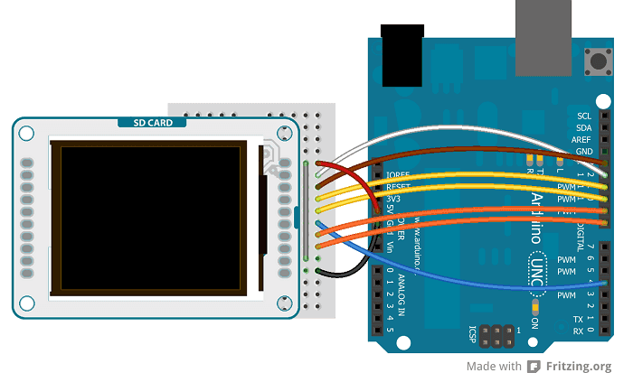
You can either connect the screen with hardware SPI pins, or define your own set of pins. Using the hardware SPI is faster when drawing to the screen.
Arduino Uno
Connect power and ground to the breadboard.
![]()
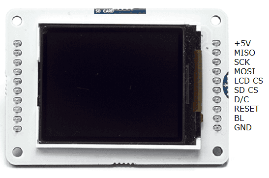
Connect the screen to the breadboard. The headers on the side of the screen with the small blue tab and arrow should be the ones that attach to the board. Pay attention to the orientation of the screen, in these images, it is upside down.
![]()
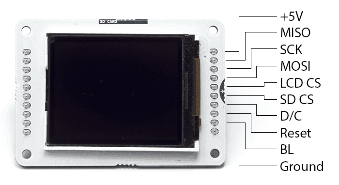
Connect the pins following this default configuration:
| +5V: | +5V |
| MISO: | pin 12 |
| SCK: | pin 13 |
| MOSI: | pin 11 |
| LCD CS: | pin 10 |
| SD CS: | pin 4 |
| D/C: | pin 9 |
| RESET: | pin 8 |
| BL: | +5V |
| GND: | GND |
Connecting the pins in the proper way, you can see the lcd screen working with your Uno (or Duemilanove) just uploading the simple "TFTBitmapLogo" sketch.
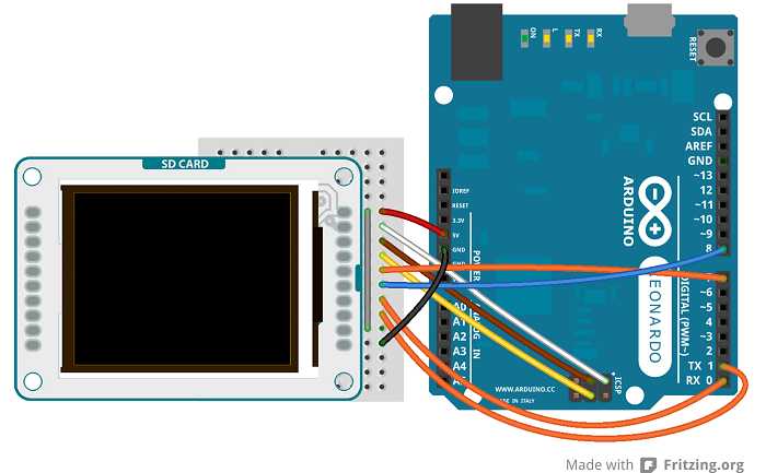
Arduino Leonardo & Arduino Yún
The Arduino Leonardo & Arduino Yún use different pins to be compatible with the lcd screen. To set the pins MISO, MOSI and SCK, you have to use the ICSP terminals.
| +5V: | +5V |
| MISO: | Miso pin (white wire on ICSP) |
| SCK: | Sck pin (brown wire on ICSP) |
| MOSI: | Mosi pin (yellow wire on ICSP) |
| LCD CS: | pin 7 |
| SD CS: | pin 8 |
| D/C: | pin 0 |
| RESET: | pin 1 |
| BL: | +5V |
| GND: | GND |
The image below shows an Arduino Leonardo but it works for an Arduino Yún too.
The screen will show this message: "Arduino TFT Bitmap Example. Open serial monitor to run the sketch". Open the serial monitor to view the Arduino Logo.
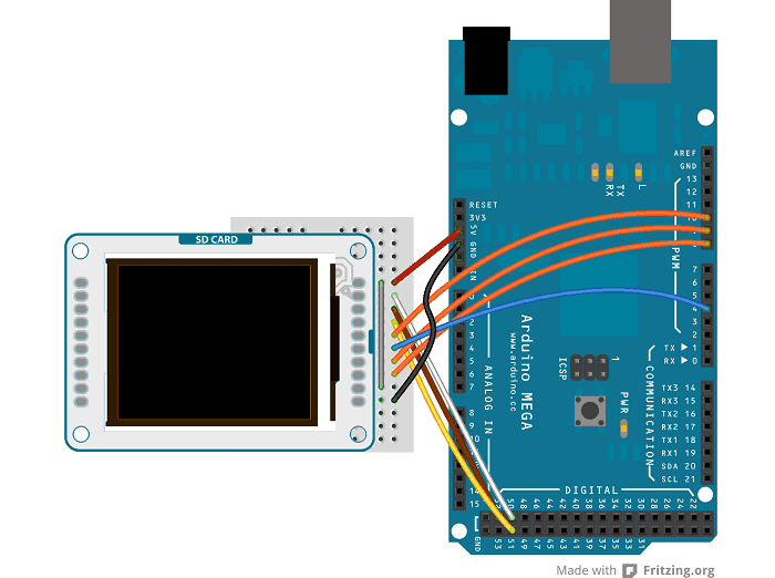
Arduino Mega 2560 or Mega ADK
To connect the lcd screen to a Mega board, use this pin configuration:
| +5V: | +5V |
| MISO: | 50 on Mega 2560 (Miso on ADK) |
| SCK: | 52 on Mega 2560 (Sck on ADK) |
| MOSI: | 51 on Mega 2560 (Mosi on ADK) |
| LCD CS: | pin 10 |
| SD CS: | pin 4 |
| D/C: | pin 9 |
| RESET: | pin 8 |
| BL: | +5V |
| GND: | GND |
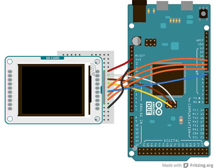
Arduino Due
To connect the lcd screen to an Arduino Due, use this pin configuration and don't forget to set the right value for the variable "sd_cs" (
#define sd_cs 7| +5V: | +3.3V |
| MISO: | Miso pin (white wire on SPI) |
| SCK: | Sck pin (brown wire on SPI) |
| MOSI: | Mosi pin (yellow wire on SPI) |
| LCD CS: | pin 10 |
| SD CS: | pin 7 |
| D/C: | pin 9 |
| RESET: | pin 8 |
| BL: | +3.3V |
| GND: | GND |
Next steps
Now that you have tested the basic functionality of the screen, see the TFT library pages for information about the library's API and additional examples. It's also recommended to visit the Adafruit graphics library page for additional information on functions not covered.
The text of the Arduino getting started guide is licensed under a Creative Commons Attribution-ShareAlike 3.0 License. Code samples in the guide are released into the public domain.
Suggest changes
The content on docs.arduino.cc is facilitated through a public GitHub repository. If you see anything wrong, you can edit this page here.
License
The Arduino documentation is licensed under the Creative Commons Attribution-Share Alike 4.0 license.