Analog Input
Use a potentiometer to control the blinking of an LED.
In this example we use a variable resistor (a potentiometer or a photoresistor), we read its value using one analog input of an Arduino board and we change the blink rate of the built-in LED accordingly. The resistor's analog value is read as a voltage because this is how the analog inputs work.
Hardware Required
Arduino Board
Potentiometer or
10K ohm photoresistor and 10K ohm resistor
built-in LED on pin 13 or
220 ohm resistor and red LED
Circuit
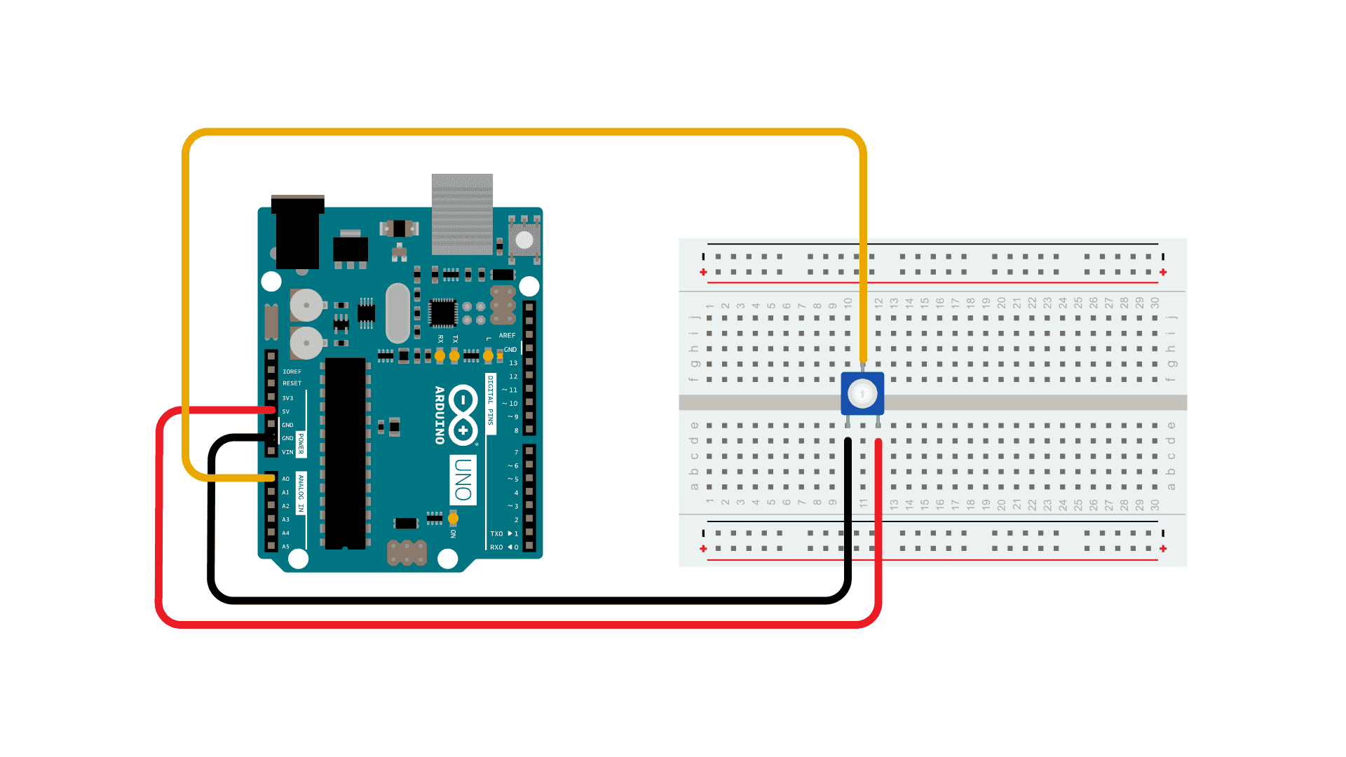
With a potentiometer
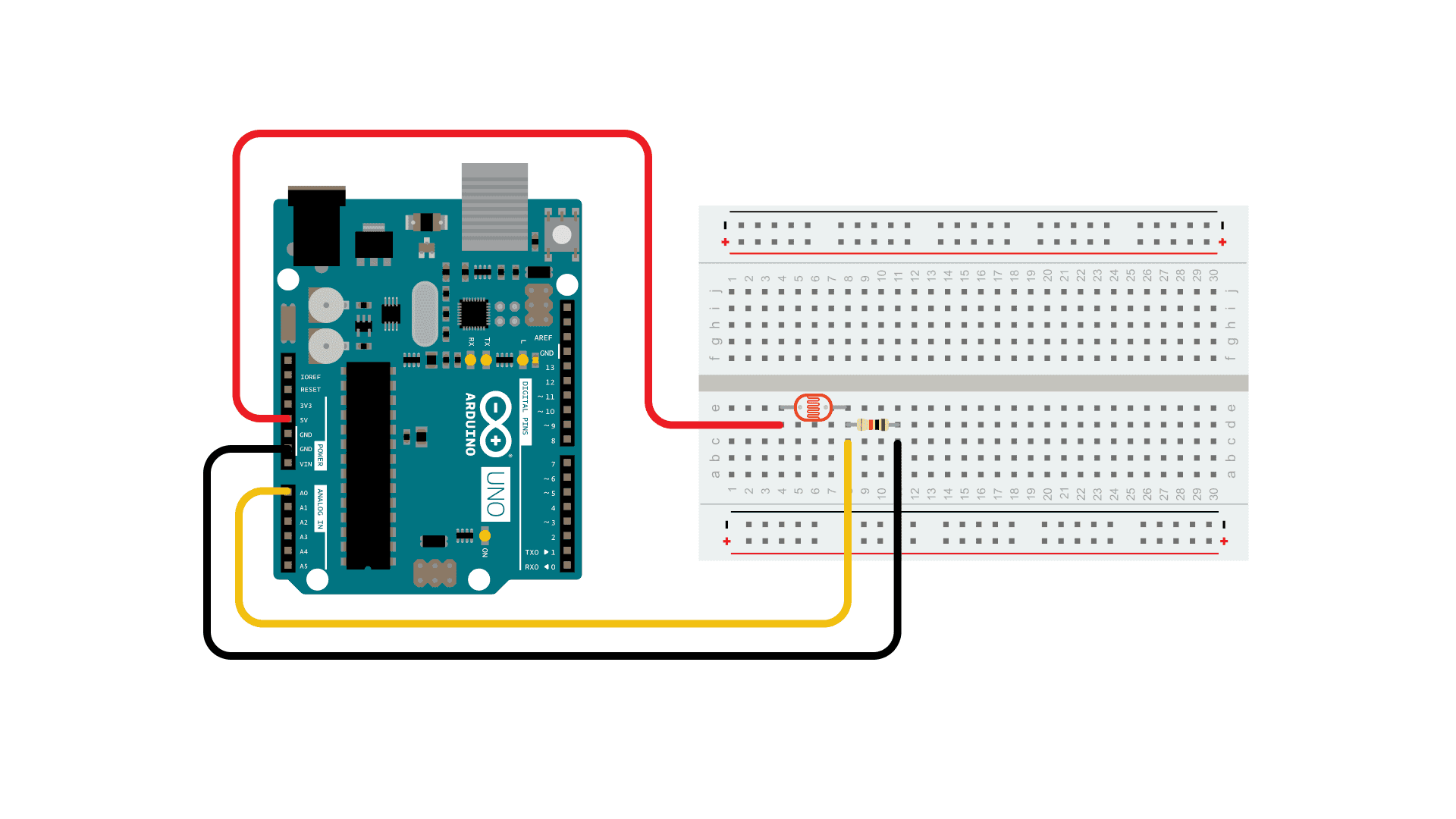
With a photoresistor
Connect three wires to the Arduino board. The first goes to ground from one of the outer pins of the potentiometer. The second goes from 5 volts to the other outer pin of the potentiometer. The third goes from analog input 0 to the middle pin of the potentiometer.
For this example, it is possible to use the board's built in LED attached to pin 13. To use an additional LED, attach its longer leg (the positive leg, or anode), to digital pin 13 in series with the 220 ohm resistor, and it's shorter leg (the negative leg, or cathode) to the ground (GND) pin next to pin 13.
The circuit based on a photoresistor uses a resistor divider to allow the high impedance Analog input to measure the voltage. These inputs do not draw almost any current, therefore by Ohm's law the voltage measured on the other end of a resistor connected to 5V is always 5V, regardless the resistor's value. To get a voltage proportional to the photoresistor value, a resistor divider is necessary. This circuit uses a variable resistor, a fixed resistor and the measurement point is in the middle of the resistors. The voltage measured (Vout) follows this formula:
Vout=Vin*(R2/(R1+R2))
where Vin is 5V, R2 is 10k ohm and R1 is the photoresistor value that ranges from 1M ohm in darkness to 10k ohm in daylight (10 lumen) and less than 1k ohm in bright light or sunlight (>100 lumen).
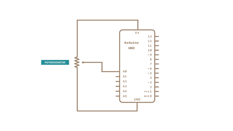
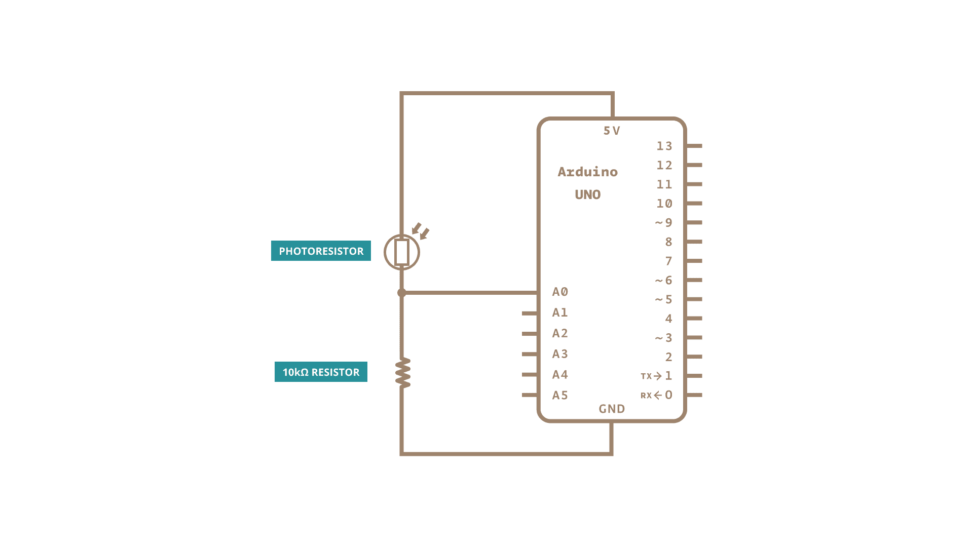
Schematic
Potentiometer
Photoresistor
Code
At the beginning of this sketch, the variable
sensorPinledPinsensorValueThe
command converts the input voltage range, 0 to 5 volts, to a digital value between 0 and 1023. This is done by a circuit inside the microcontroller called an analog-to-digital converter or ADC.analogRead()
By turning the shaft of the potentiometer, you change the amount of resistance on either side of the center pin (or wiper) of the potentiometer. This changes the relative resistances between the center pin and the two outside pins, giving you a different voltage at the analog input. When the shaft is turned all the way in one direction, there is no resistance between the center pin and the pin connected to ground. The voltage at the center pin then is 0 volts, and
analogRead()analogRead()analogRead()That value, stored in
sensorValuedelay()Learn more
You can find more basic tutorials in the built-in examples section.
You can also explore the language reference, a detailed collection of the Arduino programming language.
Last revision 2015/07/28 by SM
Suggest changes
The content on docs.arduino.cc is facilitated through a public GitHub repository. If you see anything wrong, you can edit this page here.
License
The Arduino documentation is licensed under the Creative Commons Attribution-Share Alike 4.0 license.