Monitor Your Energy Bill with Modbus and the Arduino Cloud
Connect a Modbus energy meter to an Arduino® MKR WiFi 1010 board and a MKR 485 Shield and monitor the power consumption of your home via an Arduino Cloud IoT dashboard.
Introduction
If you really want to make your home smarter, you'll probably want start from your monthly bills (for example, energy, gas, etc...). As some say: good for the planet, the wallet and the bottom line. In this tutorial, we are going to learn how to connect a Modbus energy meter to the Arduino Cloud IoT using an Arduino® MKR WiFi 1010 board and an Arduino® MKR 485 Shield.
This tutorial assumes you know the basics of the Arduino Cloud. If you are new check out our Getting Started Guide.
Goals
The goals with this tutorial are:
- Learn how to connect a Modbus energy meter to the Arduino Cloud IoT.
- Learn how to use the Arduino® MKR 485 Shield with an Arduino® MKR WiFi 1010 board.
Hardware and Software Needed
The hardware and software used in this tutorial:
- Arduino Cloud IoT.
- Arduino Create Agent.
- Arduino Modbus library
- Arduino® MKR WiFi 1010 board.
- Arduino® MKR 485 Shield.
- Finder Type 7E.64 Energy Meter.
- Twisted single pair shielded cable.
- Micro USB cable.
Electric Meters a.k.a Energy Meters
Energy consumption awareness is a key factor to reduce energy costs and improve energy efficiency; we can measure energy consuption using electric meters, a.k.a energy meters.
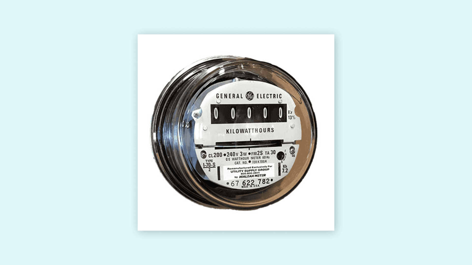
Electric meters, also known as energy meters, are electronic devices that can measure the amount of energy consumed by an electrically powered equipment such as a refrigerator or a lamp. Energy meters can be use also to measure the energy consuption of houses and buildings. While different types of energy meters exist, in this tutorial we choose a Finder Type 7E.64 Energy Meter. This energy meter is designed for DIN rail use and fits perfectly in the main cabinet of our house. Also, this energy meter has a RS-485 Modbus interface, this is an industrial communication protocol that can be decoded in Arduino boards using an Arduino MKR 485 Shield and the Arduino Modbus library.
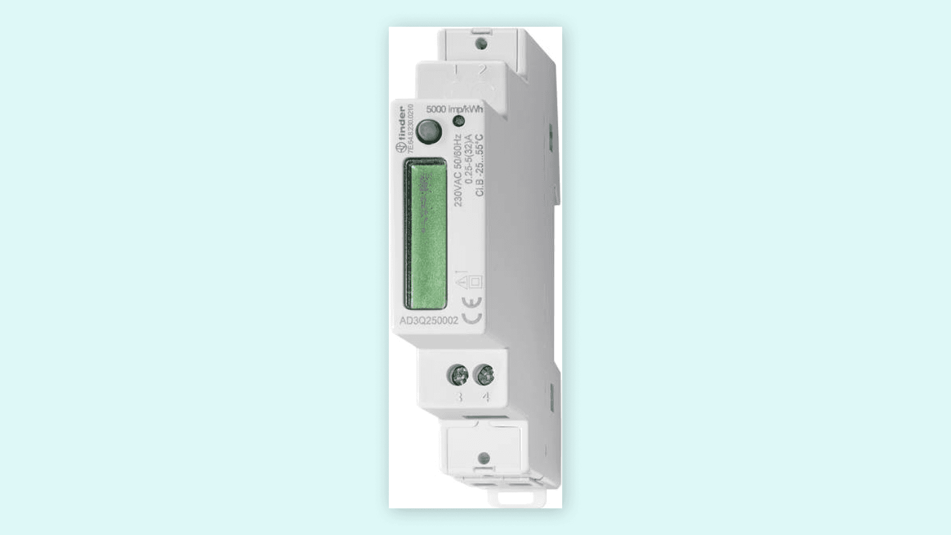
Setting Up the Finder Type 7E.64 Energy Meter
First, you must install the energy meter in your electrical cabinet. To ensure you are working in a safe environment, turn off the power from the electrical terminal ahead of your system and double check with a multimeter that there is no voltage between the terminals.
Warning! Check your country regulations about dealing with your house electrical system and be extremely careful because it can be deadly! If you don't know how, call an electrician.
Place the energy meter inside your cabinet and connect the live and neutral wires from the main breaker to the input of the meter, remember to use the standard color convention (blue for neutral and brown/black/grey for live in EU. The output has to be connected to the rest of the system.
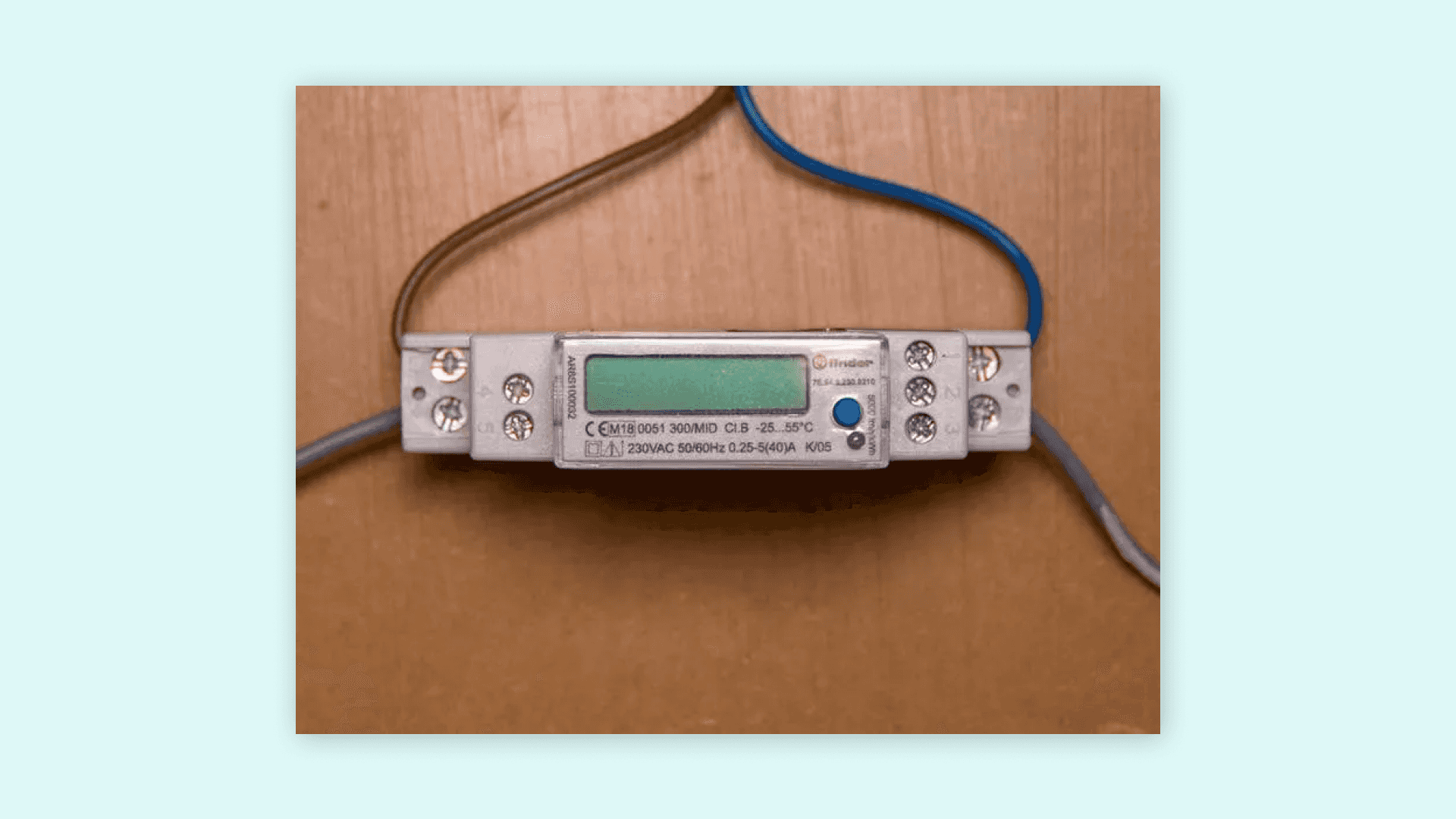
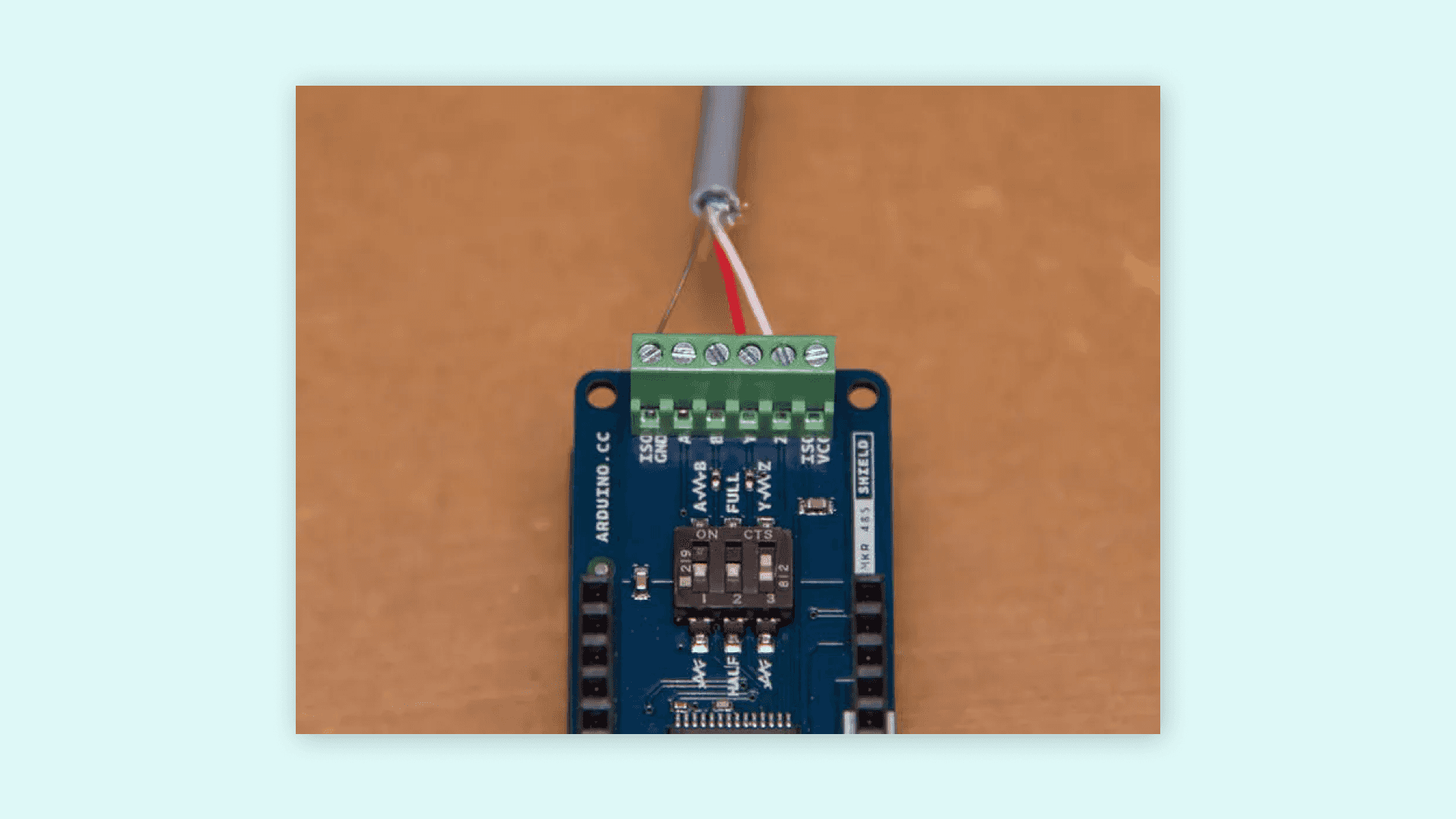
Now it is time make the connection between the energy meter and our MKR WiFi 1010 board! For this, we will use twisted single pair cable with ground. This type of cable is typically used for phone lines, so it can be used to transmit electrical signals over long distances (up to 1.2 km). However, we are going to use a cable long enough to exit the cabinet and place our MKR WiFi 1010 board in an accessible place.
The RS-485 standard names its terminals A, B and COM. A common de-facto standard is the use of TX+/RX+ (or D+) as an alternative for B (high for mark i.e. idle) and TX-/RX- (or D-) as an alternative for A (low for mark i.e. idle). As shown in the image above, we connected the red cable to the D+ terminal, the white cable to the D- terminal and the brown cable to the COM terminal of the energy meter. You can read more about the RS-485 standard here.
The Finder energy meter supports half-duplex communication, this means that data can move in two directions, but not at the same time. The MKR 485 Shield supports both half and full-duplex communication (this means data moving in two directions simultaneously), so we need to set up the shield for half-duplex communication. In the MKR 485 Shield, half-duplex communication uses Y and Z terminals, Y terminal is B or D+ and Z terminal y A or D-, this means that the red cable must be connected to Y terminal and the white cable to Z terminal; the brown cable (COM) must be connected to ISOGND terminal. Also, we need to set the second switch to HALF (2 to OFF) and the third switch to Y-Z (3 to ON): the first switch is not used in half-duplex communication. The third switch is used for setting up the termination, this is a resistor connecting the two data terminals that is used for dampening interferences. The complete shield setup is shown in the image below:
Now, we can connect the MKR 485 Shield and the MKR WiFi 1010 board:
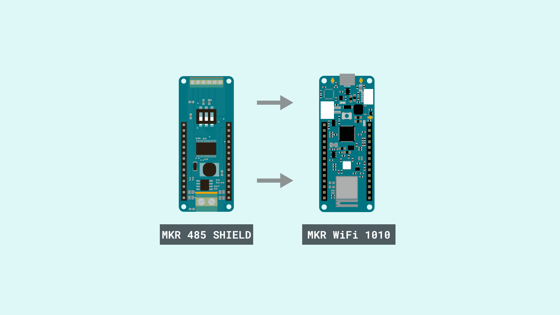
Now that we have finished setting up the hardware, it is time to connect our energy meter to the Arduino Cloud IoT
Setting Up the Arduino Cloud IoT
- Create a Thing with the following variables:
| Variable | Type | Permission | Update Policy |
|---|---|---|---|
| voltage | Floating Point Number | Read Only | On change |
| current | Floating Point Number | Read Only | On change |
| power | Floating Point Number | Read Only | On change |
| frequency | Floating Point Number | Read Only | On change |
| energy | Floating Point Number | Read Only | On change |
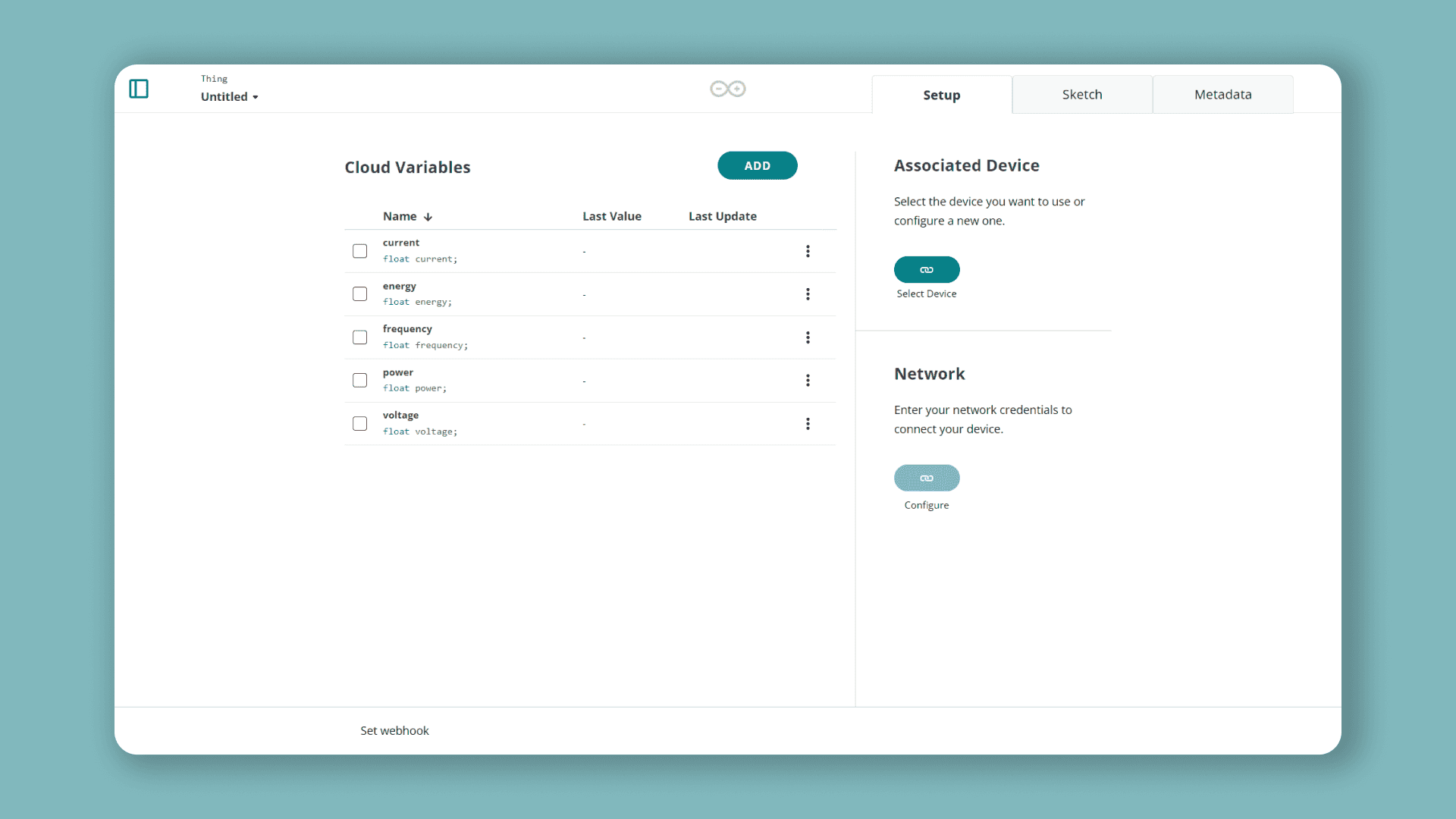
- Set up your MKR WiFi 1010 and configure your network credentials.
Creating a Sketch for a "Thing" in the Arduino Cloud IoT
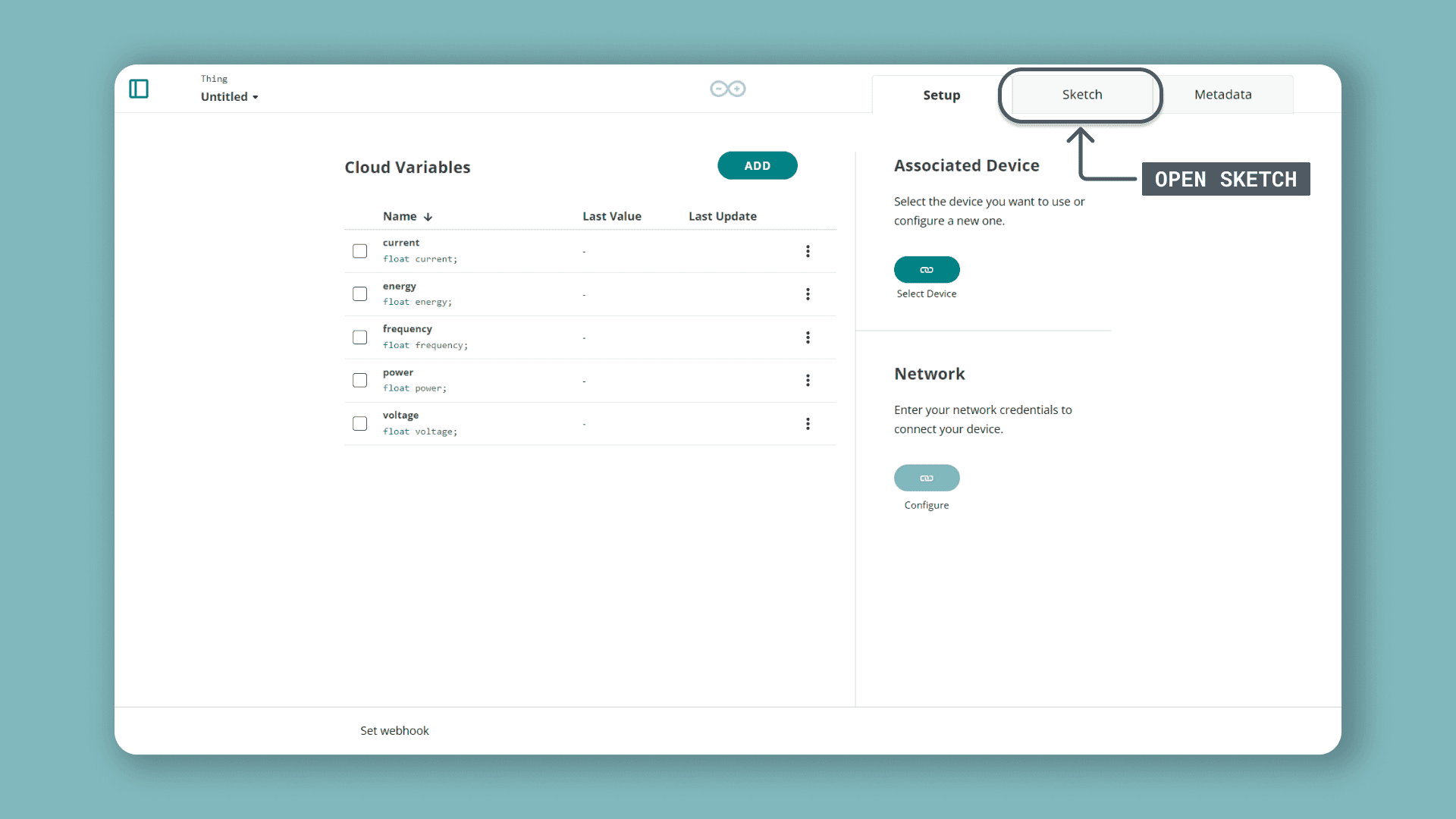
Once we are finished with all the configurations of the "Energy Thing", we can move on to creating the sketch that we are going to upload to our MKR WiFi 1010 board. To do so, we first need to go to the "Sketch" tab. But before, let's talk about Modbus.
Modbus is an open source communication protocol designed specifically for industrial sensors and machines. In simple terms, it is a method used for transmitting information over serial lines between electronic devices. Our MKR WiFi 1010 board can talk Modbus using the Arduino Modbus library. This library packs all the handlers and makes hooking up any Modbus device to some of the Arduino® boards (like the MKR family boards) really fast and easy. You can read more about Modbus here.
In the datasheet of the energy meter we can find all the Modbus related information we need like its function codes, address of its registers and also their sizes.
Modbus messages follow a simple structure, for example:
01 03 04 00 16 00 02 25 C7In this structure:
is the device address.0x01
is the function code that tells the Modbus device if we want to read or write data. In this tutorial, we want to read data from the holding registers of the energy meter.0x03
for byte count, this specifies how may data items are being returned.0x04
is register address from the Modbus device we want to read.00 16
is the size of the register in words (every word is 2 bytes long).00 02
is a CRC code. This code is generated from a math function over previous bytes, it ensures that the message has been received correctly.25 C7
The Arduino Modbus library handles this structure. For example, for reading the register of the energy meter that holds information about current, we have the following function that uses the
requestFrom()1/* 2Function readCurrent()3Description: read current value from the Finder energy meter holding registers4
5Created by Alberto Perro (Officine Innesto)6Modified by José Bagur7*/8
9float readCurrent() { 10 float ampere = 0.;11 // Send reading request over RS485 12 if (!ModbusRTUClient.requestFrom(0x01, HOLDING_REGISTERS, 0x0016, 2)) {13 // Error handling 14 Serial.print("- Failed to read the current! "); 15 Serial.println(ModbusRTUClient.lastError()); 16 } else { 17 // Response handler 18 uint16_t word1 = ModbusRTUClient.read(); // Read word1 from buffer19 uint16_t word2 = ModbusRTUClient.read(); // Read word2 from buffer20 int32_t milliamp = word1 << 16 | word2; // Join word1 and word2 to retrieve current value in milliampere21 ampere = milliamp/1000.0; // Convert current to ampere22 } 23return ampere;24}In the
elseThe complete sketch we are going to upload to out MKR WiFi 1010 board can be found below, notice that the Arduino Cloud IoT generated automatically the code that is dedicated to handling Internet connectivity:
1/* -----------------------------------------2 * Finder Energy Meter to Arduino Cloud IoT3 * -----------------------------------------4 * This sketch provides a full bridge between the Finder energy meter and the 5 * Arduino Cloud IoT. This sketch was developed to monitor electricity costs 6 * and usage in Casa Jasmina.7 *8 * Created by Alberto Perro (Officine Innesto)9 * Modified by José Bagur10*/11 12#include <ArduinoRS485.h>13#include <ArduinoModbus.h>14
15#undef ON16#undef OFF17
18#include "thingProperties.h"19
20unsigned long rate = 60000; // Default refresh rate in ms21unsigned long lastMillis = 0;22
23void setup() {24 // Initialize serial port at 9600 bauds and wait for it to open25 Serial.begin(9600);26 delay(1500); 27
28 // Defined in thingProperties.h29 initProperties();30
31 // Connect to Arduino Cloud IoT32 ArduinoCloud.begin(ArduinoIoTPreferredConnection);33 34 /*35 The following function allows you to obtain more information36 related to the state of network and Cloud IoT connection and errors37 The higher number the more granular information you’ll get38 The default value is 0 (only errors)39 Maximum is 440 */41 setDebugMessageLevel(2);42 ArduinoCloud.printDebugInfo();43 44 // Start Modbus RTU client45 if (!ModbusRTUClient.begin(9600)) {46 Serial.println("- Failed to start Modbus RTU Client!");47 while (1);48 }49}50
51void loop() {52 // Update "Energy Thing" variables connected to Arduino Cloud IoT53 ArduinoCloud.update();54 55 // Update energy meter data and show it via the Serial Monitor56 if (millis() - lastMillis > rate) {57 lastMillis = millis();58 59 voltage = readVoltage();60 delay(100);61 current = readCurrent();62 delay(100);63 power = readPower();64 delay(100);65 frequency = readFreq();66 delay(100);67 energy = readEnergy();68 69 Serial.print("- " + String(voltage, 3) + "V " + String(current, 3) + "A " + String(power, 3) + "W ");70 Serial.println(String(frequency, 3) + "Hz " + String(power, 3) + "kWh");71 delay(100);72 } 73}74
75/* Functions to read Finder energy meter holding registers76 * For more information: https://gfinder.findernet.com/public/attachments/7E/EN/PRT_Modbus_7E_64_68_78_86EN.pdf77 */78
79/* 80Function readVoltage()81Description: read voltage value from the Finder energy meter holding registers82*/ 83float readVoltage() {84 float volt = 0.;85 // Send reading request over RS485 86 if (!ModbusRTUClient.requestFrom(0x01, HOLDING_REGISTERS, 0x000C, 2)) {87 // Error handling88 Serial.print("- Failed to read the voltage! ");89 Serial.println(ModbusRTUClient.lastError()); 90 } else {91 // Response handler 92 uint16_t word1 = ModbusRTUClient.read(); // Read word1 from buffer93 uint16_t word2 = ModbusRTUClient.read(); // Read word2 from buffer94 uint32_t millivolt = word1 << 16 | word2; // Join word1 and word2 to retrieve voltage value in millivolts95 volt = millivolt/1000.0; // Convert to volts96 }97
98 return volt;99}100
101/* 102Function readCurrent()103Description: read current value from the Finder energy meter holding registers104*/105float readCurrent() { 106 float ampere = 0.;107 // Send reading request over RS485 108 if (!ModbusRTUClient.requestFrom(0x01, HOLDING_REGISTERS, 0x0016, 2)) {109 // Error handling 110 Serial.print("- Failed to read the current! "); 111 Serial.println(ModbusRTUClient.lastError()); 112 } else { 113 // Response handler 114 uint16_t word1 = ModbusRTUClient.read(); // Read word1 from buffer115 uint16_t word2 = ModbusRTUClient.read(); // Read word2 from buffer116 int32_t milliamp = word1 << 16 | word2; // Join word1 and word2 to retrieve current value in milliampere117 ampere = milliamp/1000.0; // Convert current to ampere118 }119
120 return ampere;121}122
123/* 124Function readPower()125Description: read power value from the Finder energy meter holding registers126*/127double readPower() {128 double watt = 0.;129 // Send reading request over RS485130 if (!ModbusRTUClient.requestFrom(0x01, HOLDING_REGISTERS, 0x0025, 3)) {131 // Error handling 132 Serial.print("- Failed to read power! ");133 Serial.println(ModbusRTUClient.lastError());134 } else {135 // Response handler 136 uint16_t word1 = ModbusRTUClient.read(); // Read word1 from buffer137 uint16_t word2 = ModbusRTUClient.read(); // Read word2 from buffer138 uint16_t word3 = ModbusRTUClient.read(); // Read word3 from buffer139
140 uint64_t milliwatt;141
142 // Join word1 and word2 to retrieve power value in milliwatt143 if (word1 >> 7 == 0) {144 milliwatt = word1 << 32 | word2 << 16 | word3;145 } else {146 word1 &= 0b01111111;147 milliwatt = 0b1 << 48 | word1 << 32 | word2 << 16 | word3;148 }149
150 watt = milliwatt/1000.; // Convert power to watts151 }152
153 return watt;154}155
156/* 157Function readFreq()158Description: read frequency value from the Finder energy meter holding registers159*/160float readFreq() {161 float freq = 0.;162 // Send reading request over RS485163 if (!ModbusRTUClient.requestFrom(0x01, HOLDING_REGISTERS, 0x0040, 2)) {164 // Error handling 165 Serial.print("- Failed to read frequency! ");166 Serial.println(ModbusRTUClient.lastError());167 } else {168 // Response handler 169 uint16_t word1 = ModbusRTUClient.read(); // Read word1 from buffer170 freq = word1/1000.0; // Retrieve frequency value171 }172 return freq;173}174
175/* 176Function readEnergy()177Description: read energy value from the Finder energy meter holding registers178*/179double readEnergy() {180 double kwh = 0.;181 // Send reading request over RS485182 if (!ModbusRTUClient.requestFrom(0x01, HOLDING_REGISTERS, 0x0109, 3)) {183 // Error handling 184 Serial.print("- Failed to read energy! ");185 Serial.println(ModbusRTUClient.lastError());186 } else {187 // Response handler 188 uint16_t word1 = ModbusRTUClient.read(); // Read word1 from buffer189 uint16_t word2 = ModbusRTUClient.read(); // Read word2 from buffer190 uint16_t word3 = ModbusRTUClient.read(); // Read word3 from buffer191 uint64_t dwh = word1 << 32 | word2 << 16 | word3; // Join word1 and word2 to retrieve energy value in dwh192 kwh = dwh/10000.0; // Convert energy to kwh193 }194 return kwh;195}Over the Air Uploads
Did you know that the Arduino Cloud supports over the air uploads? When you've uploaded a sketch to your board once, it will become available for you to upload a new sketch to the board without connecting it to your computer!
Over the Air uploads require an Entry plan to the Arduino Cloud
To use this feature, make sure the board has power. If your board is already connected to the Cloud, you will be able to upload to it over the air. Navigate to the Things sketch tab in the Arduino Cloud interface, and you should see it being discovered just as if it was connected via USB.
Creating a Dashboard in the Arduino Cloud IoT
After our code has been successfully uploaded to our board, we we will need to create a dashboard for visualizing the energy meter data.
Create a dashboard with the following widgets:
| Widget | Linked Variable |
|---|---|
| Value | voltage |
| Value | current |
| Value | power |
| Value | frequency |
| Value | energy |
Your dashboard should look something like this:
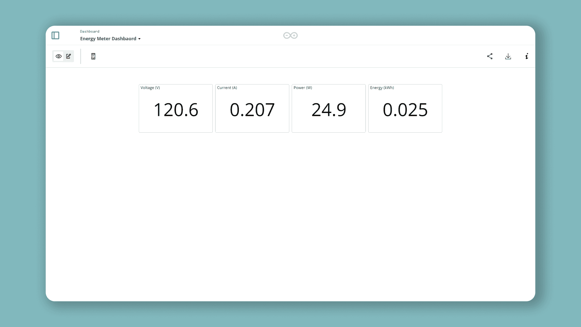
That's it! You have now a Modbus energy meter connected to the Arduino Cloud IoT!
Troubleshoot
Sometimes errors occur, if the code is not working or data is not in the to the Arduino Cloud IoT there are some common issues we can troubleshoot:
- Missing a bracket or a semicolon.
- Accidental interruption of cable connection.
- Wrong network credentials.
- No variable linked to a widget.
Conclusion
In this tutorial, we learned how to connect a Modbus energy meter to the Arduino Cloud IoT using a MKR WiFi 1010 board and a MKR 485 Shield. We also learned how to visualize the energy meter data in a dashboard using widgets. More tutorials? You can find them in the Arduino Cloud IoT documentation page.
Suggest changes
The content on docs.arduino.cc is facilitated through a public GitHub repository. If you see anything wrong, you can edit this page here.
License
The Arduino documentation is licensed under the Creative Commons Attribution-Share Alike 4.0 license.